

 WS39 casing tooth
 JM cutter tooth
 B47K22 bullet tooth
Zaozhuang · On-site fitting record
An existing barrel refitted with MH-3 roller bits.
DRILLNOVA · Field report · Updated
MH-3 roller bits fitted to the existing shell, with corrected mounting openings and a positioning reference made on site. Follow the people, measurements and welding sequence behind the completed fitting work in Zaozhuang.
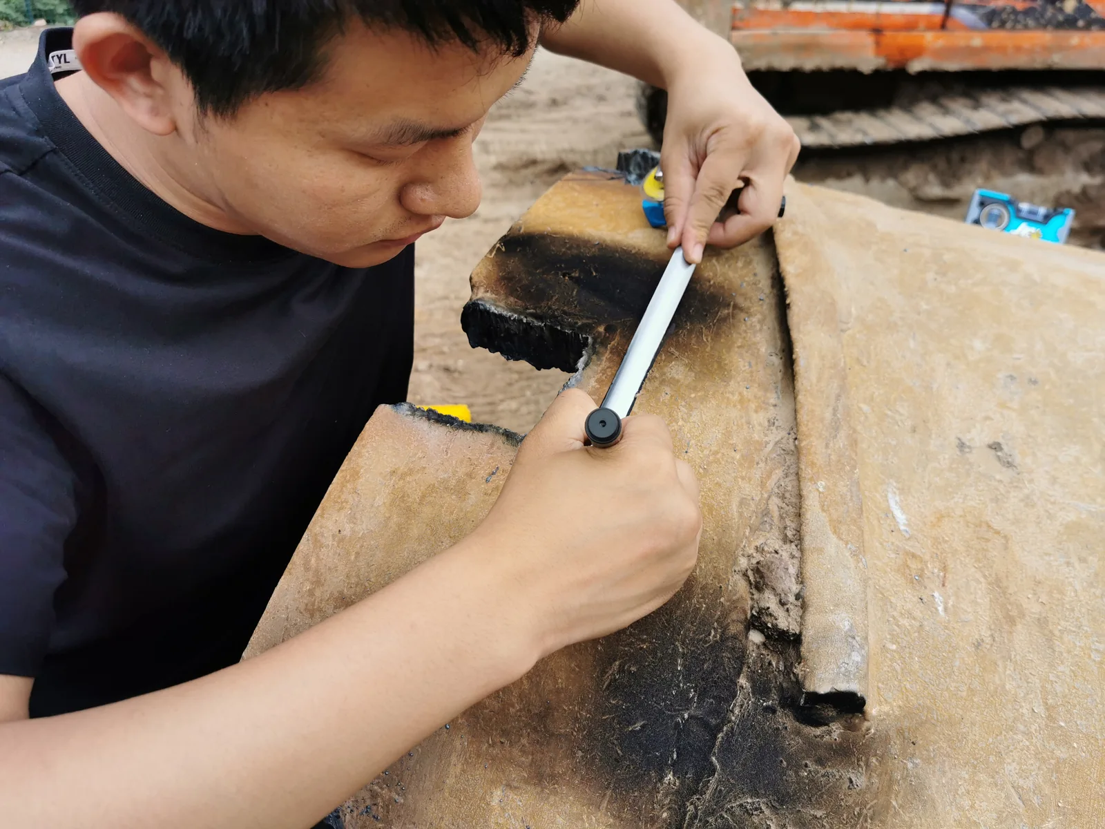
Fit the replacement bits to the actual barrel
The job took place at the construction site with the existing barrel retained. The preparation list included measuring tools, a welding drawing and a written and illustrated welding guide. Instead of using the prepared jig, the work used a centre jig made on site from reinforcing bar and steel strips.
After the existing roller bits were removed, the mounting openings were marked for correction. This gave the positioning work a defined starting point on the actual shell.
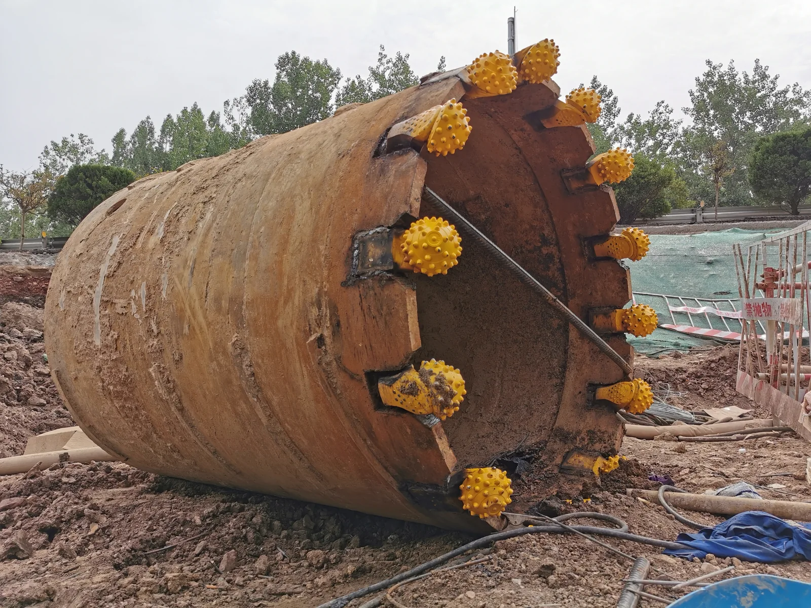
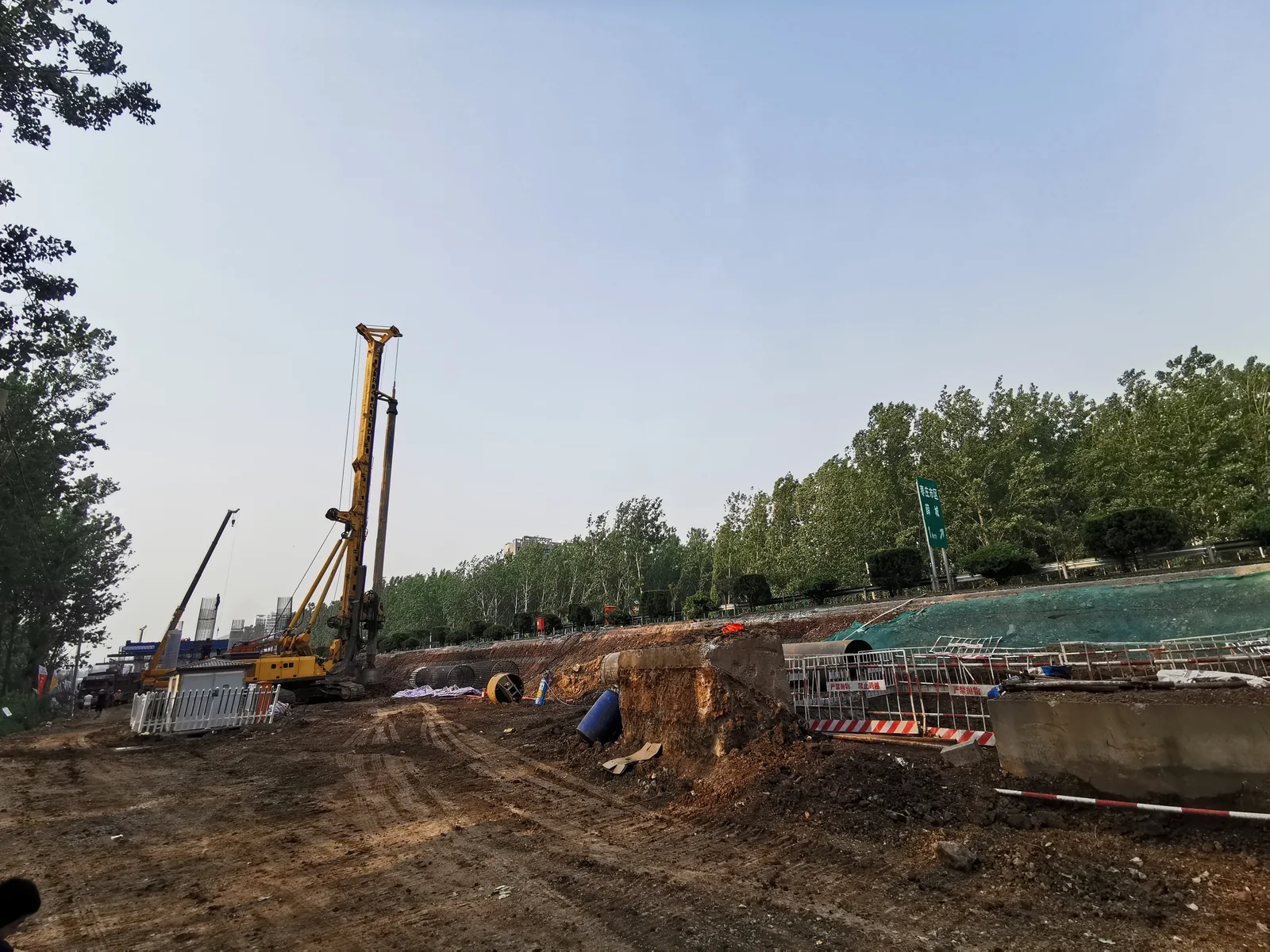
Make the reference visible, then check it
The site-made jig spanned the barrel opening. The next recorded step was to correct the jig before tack-fixing the replacement bits. The paired photographs show the whole reference and a closer measurement view.
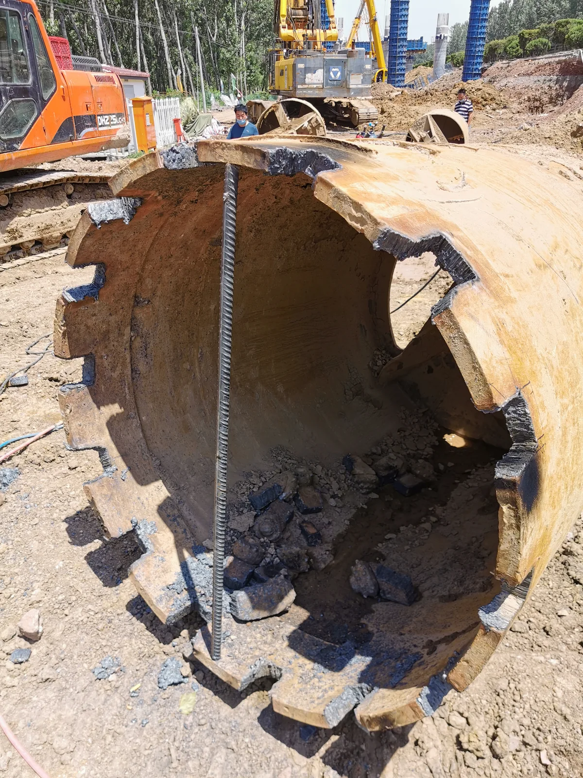
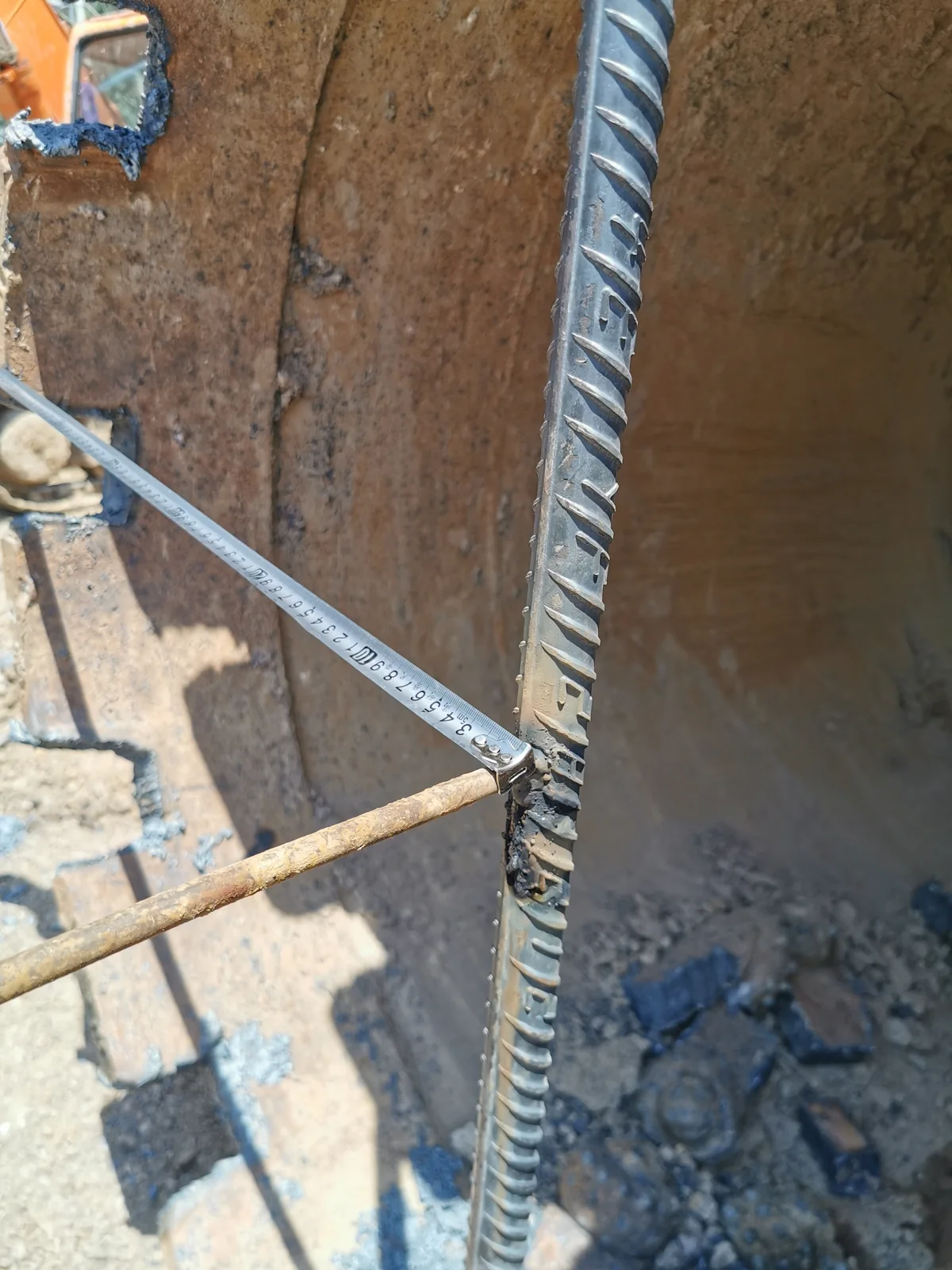
For a buyer planning a rebuild, this is the practical distinction between supplying a replacement roller bit and establishing how it will be fitted: the reference, the mounting opening and the bit position need to be considered together.
Keep the position through the welding sequence
The record separates tack fixing from the subsequent welding. It also explicitly notes cooling during the welding stage. These photographs show the work in progress before the completed-assembly view at the top of the report.
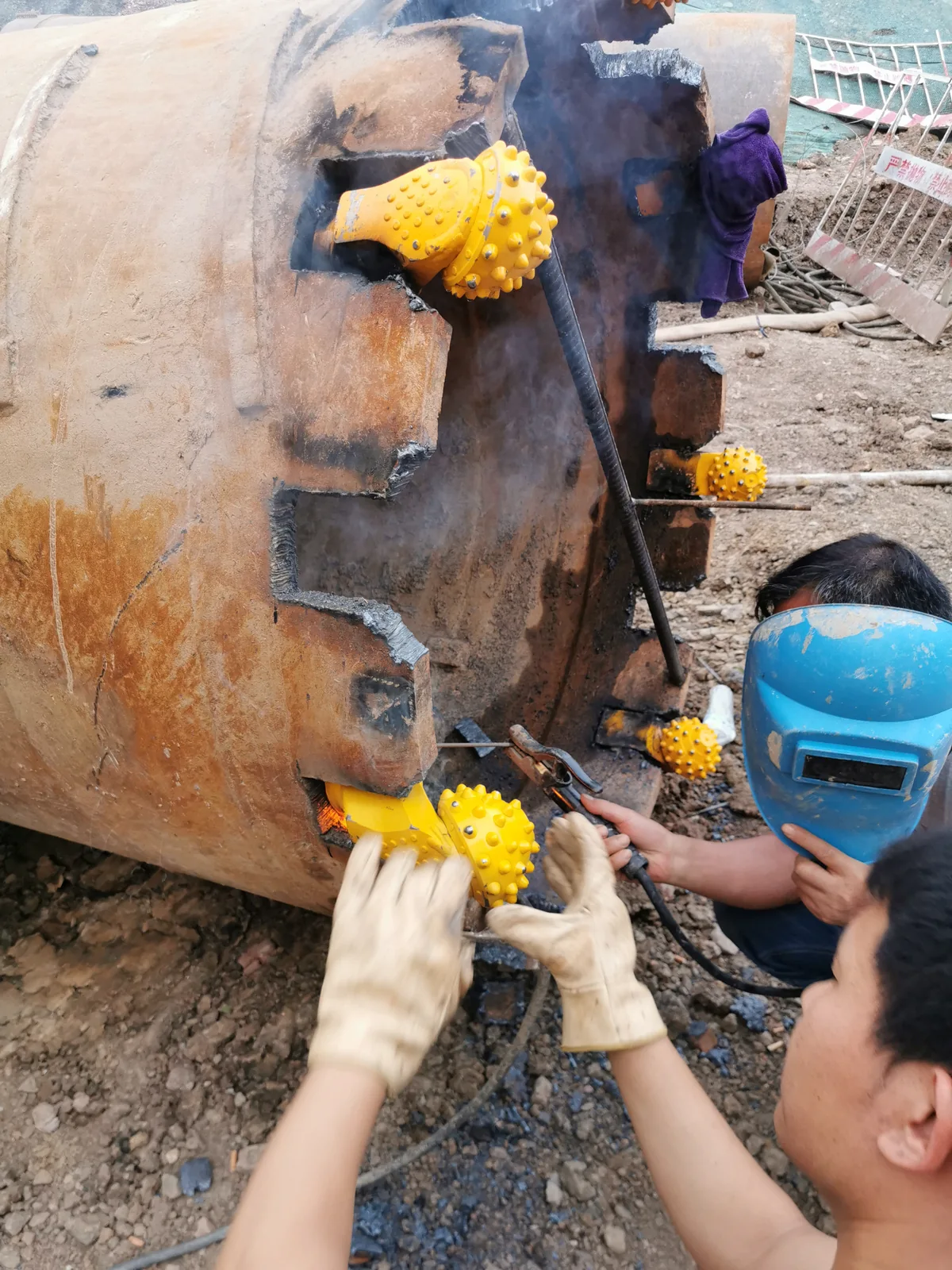
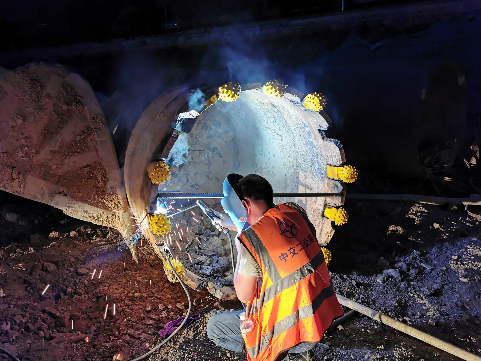
The work connects the positioning reference to the mounting welds, with the actual crew, tools and barrel visible throughout the sequence.
View the original six-step work sequence
The sequence recorded at the site
- Cut away the existing roller bits.
- Mark the openings for correction.
- Place the reinforcing-bar and steel-strip jig.
- Correct the jig.
- Tack-fix the roller bits.
- Complete the mounting welds, with attention to cooling.
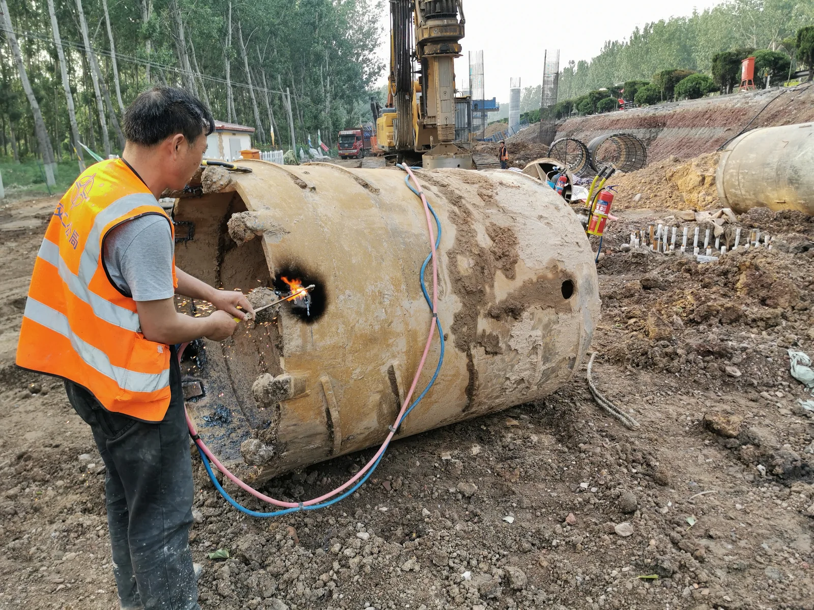
This record documents fitting and welding, rather than a drilling trial. It does not include post-refit drilling distance, service-life results or final inspection readings. For a new rebuild, confirm the current cutter drawing and welding procedure for that job.
Plan the fitting before replacement
Replacing roller bits on an existing barrel?
Send the barrel diameter, a full view of the cutting end, close-ups of the mounting openings and the roller-bit reference or drawing. Those details help us discuss the fitting scope and the positioning references for your tool.