

 WS39 casing tooth
 JM cutter tooth
 B47K22 bullet tooth
DRILLNOVA / ROTARY DRILLING TOOLS
Core barrels
Two cutting configurations. Choose bullet teeth and holders or roller bits, then define the complete barrel, replacement lower assembly or conversion scope.
Choose your core-barrel configuration
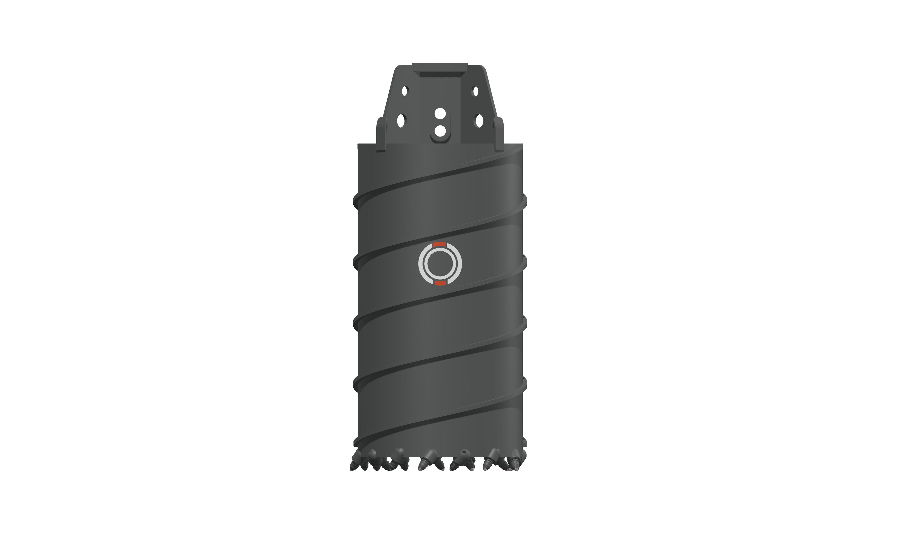
BULLET-TOOTH CONFIGURATION
Bullet-tooth core barrels
Teeth, holders and retention parts form the cutting assembly. Review projection, holder seating and the cutting layout as one assembly.
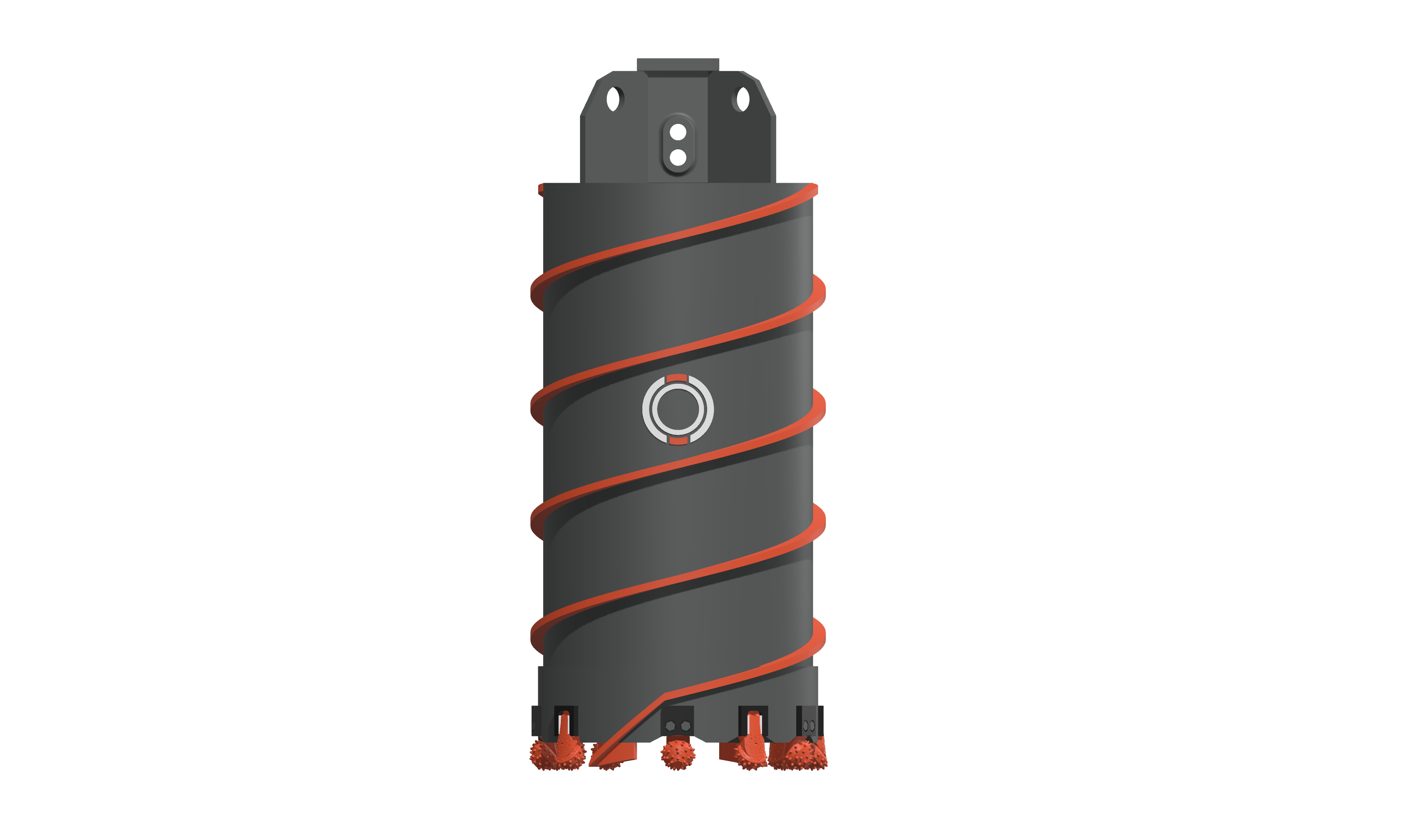
ROLLER-BIT CONFIGURATION
Roller-bit core barrels
Cones, legs or mounting interfaces establish the cutting paths around the ring. Review their working height and the surrounding assembly together.
Compare the complete cutting arrangement
Roller-bit and bullet-tooth core barrels both form an annular cut. The important difference is the cutting assembly carried by the cutting ring. Roller-bit legs establish the positions of the cones and their inserts. Bullet teeth sit in holders, with the tooth, holder and retention parts forming the installed cutting set.
Keep the nominal pile diameter, supporting-ring dimensions and actual cutting paths separate. The tool also has to work with the method used to break, recover and clear the core. Those relationships make a useful starting point for comparing a new barrel with a cutting-ring replacement or conversion.
| Review point | Roller-bit arrangement | Bullet-tooth arrangement |
|---|---|---|
| Positioning | Inner and outer cutting paths, leg orientation and cutter working height. | Holder position, tooth projection and the repeated inner/middle/outer arrangement where specified. |
| Replacement interface | Leg or mounting interface and the condition of its supporting opening. | Tooth shank, holder seat and retaining components. |
| Condition record | Cone movement, insert/leg damage and the surrounding ring, guides and scrapers. | Tip/body wear, tooth seating and movement, holder wear and retention condition. |
| Conversion scope | Review retained steelwork and both cutting paths before choosing cutter-only work, a replacement cutting ring or a complete tool. | |
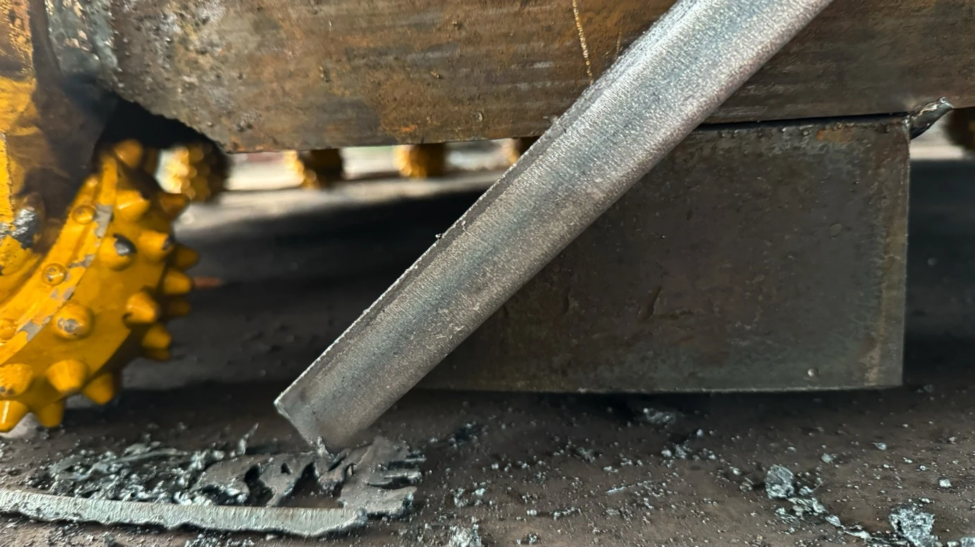
Check the assembled cutting arrangement
The documented 1,800 mm build combined 16 roller bits and four scrapers. The workshop established the first inner and outer positions from common layout references, then remeasured the full set and adjusted individual cutters.
Record the drawing target and actual position together. Check the relationship between cutters, scrapers and guides as well as each individual component. These photographs document assembly work; the selected drawing defines the required geometry.
Compare the complete drilling cycle
The Jieyang high-spiral trial followed cutting, clearing and core recovery together. Good cuttings discharge was reported, while breaking and recovering the core still influenced the full cycle. Record active cutting, lifting, clearing and recovery separately when comparing working methods. See the recovered rock and operating review.
Planning a large-diameter pile? Our 2,000 mm design review compares five working diameters with a three-stage proposal, including cutting paths, guidance and core recovery. See how the staged-drilling proposal was assessed.
The comparison above identifies configuration and inspection differences. Ground description, rig interface and the actual trial remain part of selection; it does not assign a universal performance range to either arrangement.
USE & APPLICATION
Work through the practical checks.
PRODUCT & PROJECT ENQUIRY
Discuss a complete barrel or conversion scope
Send the required barrel size, drive connection, ground conditions and existing tool photographs. Identify whether you need a complete barrel, a replacement cutting ring or cutting parts.