

 WS39 casing tooth
 JM cutter tooth
 B47K22 bullet tooth
Identify the damaged part first: a missing carbide insert and a missing cone require different checks. If the cone remains attached, record its movement and insert condition separately.
Cone loss
The cone is missing. The leg remains.
Take the tool out of service and follow the site’s procedure for a missing component in the bore. Support and isolate the recovered tool before inspection. Keep any recovered parts for the review.
Start with the leg tip and journal
Photograph the remaining leg from the front and both sides. Include the journal that carried the cone, the leg tip and the adjacent cutters.
- If the leg tip is heavily worn: check the mounting position, contact marks, cutting envelope and packed cuttings as well as the bearing area.
- If the leg tip shows little wear: keep bearing fit, sealing, lubrication and welding history in the review. Lack of tip wear does not establish which of these caused the loss.
Wear patterns guide the next inspection; they do not establish the cause.
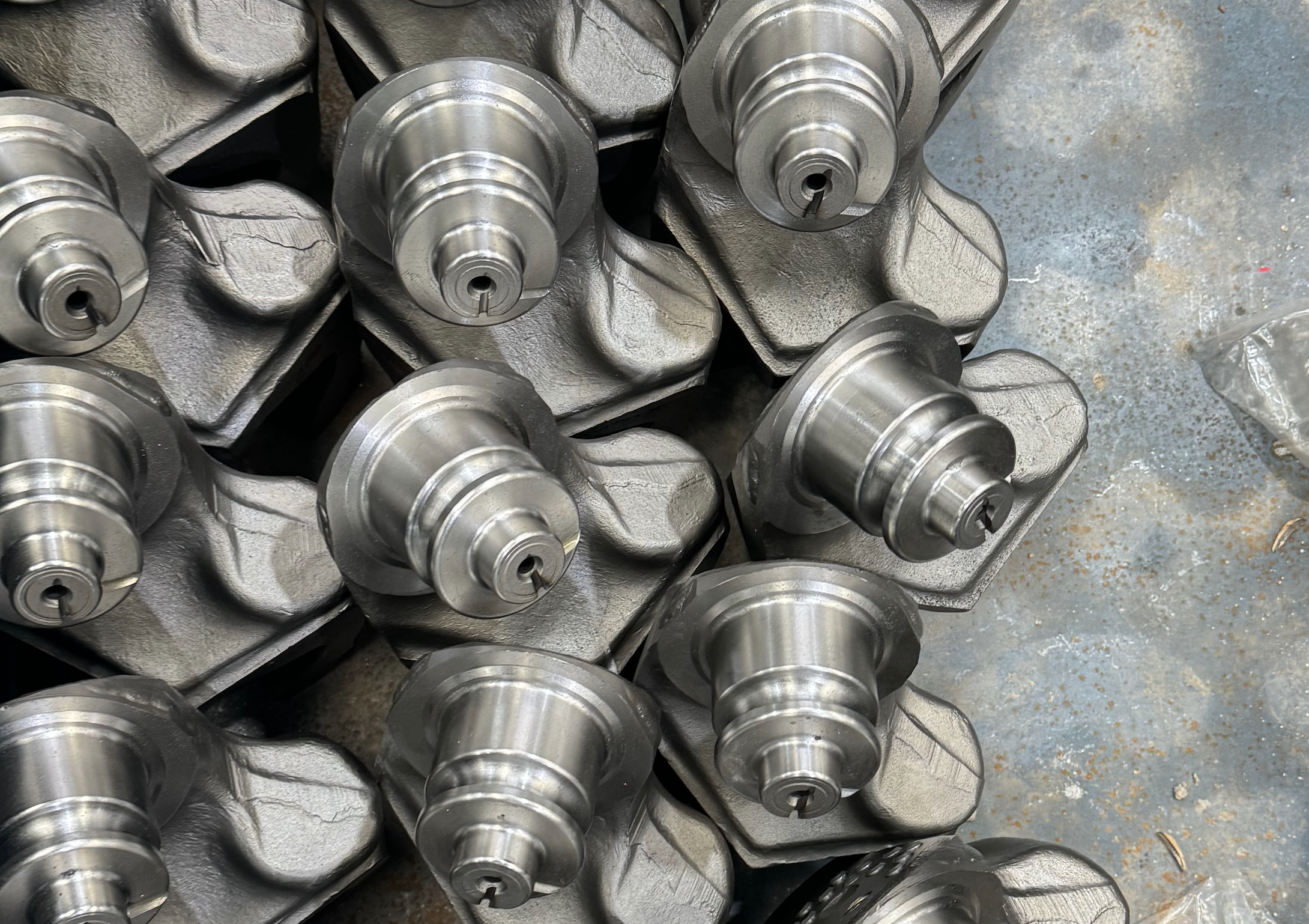
Could bearing or seal damage be involved?
Loss of sealing or effective lubrication can be followed by internal wear and increasing cone movement. In some cases, damage may progress to cone separation. A cone that starts turning again after sticking does not demonstrate that its seal or bearing has recovered.
This is a possible mechanism, not a confirmed sequence for your tool. The remaining journal, recovered parts, fit measurements, welding history and operating record are needed to distinguish the causes. Photograph the condition before cleaning; do not grind away damaged surfaces before they have been assessed.
The cone is still attached, but it sticks or rocks
Record whether movement is consistently rough, tight at one position, seized or noticeably loose. Stop using the affected tool and inspect it only when safely supported and isolated. Do not add drilling force to test whether a sticking cone will free itself.
Note when the change first appeared: after welding, after a change in ground, or during an interval with packed cuttings or unusual vibration. Compare neighbouring cones at the same inspection. Turning by hand cannot establish acceptable bearing clearance or confirm that the seal is intact.
See the seized-cone teardown photos or review the bearing measurements behind a movement check.
Workshop inspection
A seized cone, opened for inspection
In this seized roller bit, many carbide inserts were still present. Dismantling revealed a different condition inside: the inspection notes recorded a damaged seal, deformed steel balls—including one split in two—and wear on the journal and ball race.
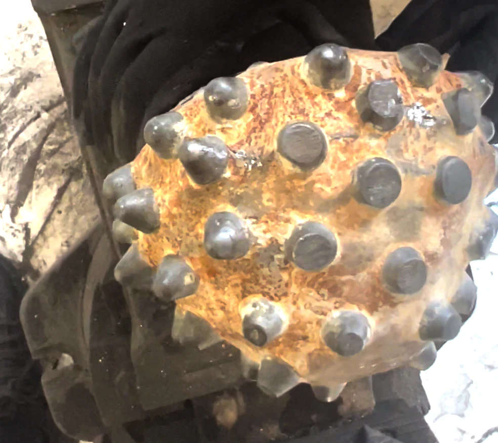
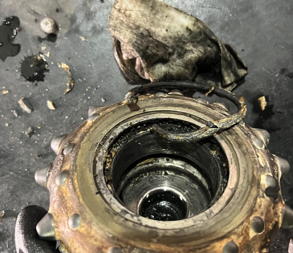
What the teardown established—and what it did not
Observed and recorded: external carbide condition and internal bearing condition differed. Keep the cone, seal remnants and recovered balls identified to the same roller bit so that their condition can be assessed together.
Still to investigate: the original analysis proposed loss of sealing and debris entry. Welding heat, packed cuttings affecting cooling, seal condition and operating settings were possible contributors, not confirmed causes. A darkened seal does not by itself establish the temperature or when the damage occurred.
The record did not establish that the installation angle was correct, or provide an operating history sufficient to calculate service life. The next review needs the mounting position, welding history, first symptom and operating conditions, as well as the recovered parts.
What is visible at the affected insert?
Photograph the insert or empty pocket closely. Distinguish remaining carbide from surrounding steel, and record wear in both.
Keep the original image and the marked location together. Avoid turning an empty pocket into a claim that an intact insert pulled out: the earlier condition may not have been observed.
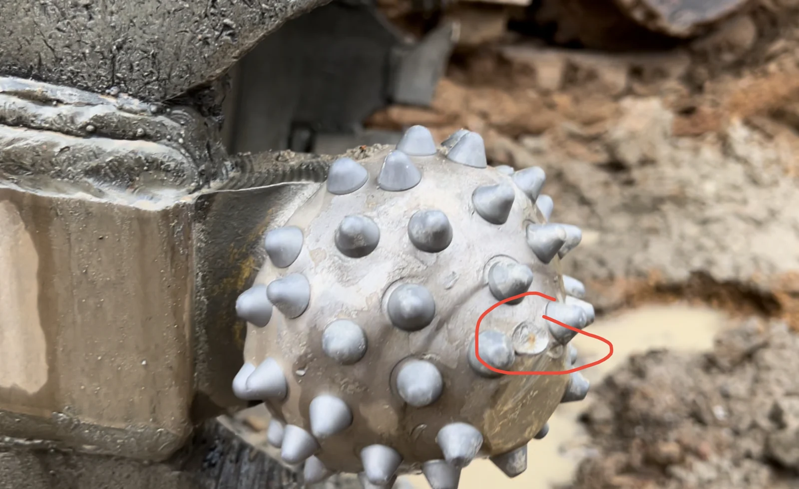
Where was the roller bit working in the complete tool?
Number the roller bits and identify inner or outer positions. Record the neighbouring cutters, scrapers, spoil guides and cone movement, then connect the close-up to a full-tool view.
Keep inspections from different dates separate. Add the earliest known symptom, ground interval, cutter changes, operating settings, cleaning conditions and welding history to the position record.
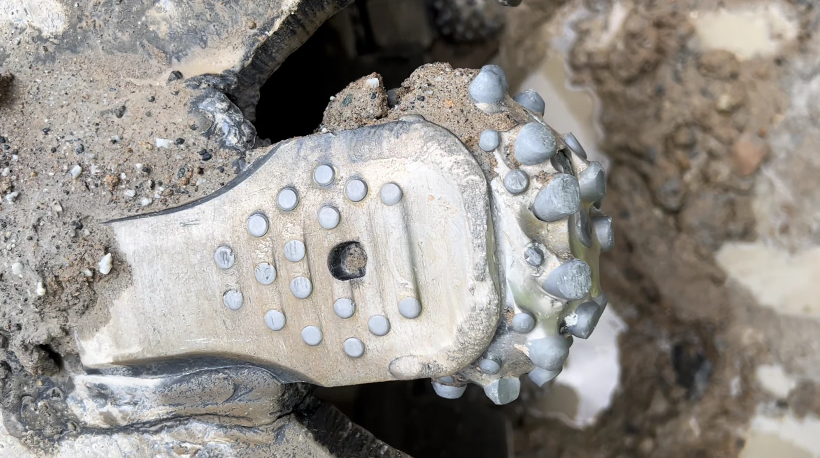
Does the same side keep wearing?
When side wear at the leg tip returns after cutter replacement, extend the inspection beyond the new bit. Play in the Kelly-bar connections or square drive can contribute to sideways contact between the cutting assembly and the bore wall. Changing the roller bit alone does not correct that movement.
With the tool safely supported and isolated, map the worn side on each affected leg. Compare that pattern with marks on the shell and guides, then have the rig team inspect the Kelly connections, square drive and barrel connection against their service limits. Record where movement is found rather than describing the complete assembly simply as “loose”.
Wear marks identify a direction to investigate. They do not, on their own, prove excessive drive play or exclude abrasive cuttings and incorrect cutter positioning.
Which checks follow the first sign of damage?
| First observation | Potential contributor / record to check | Check before returning the tool to service |
|---|---|---|
| A fresh broken insert, followed by more impact marks | Loose carbide or other hard debris left in the hole. | Follow the project’s hole-cleaning procedure; retain recovered fragments and compare them with the numbered damaged positions. |
| An empty pocket with heavily worn surrounding steel | Loss of steel support around the insert. | Photograph pocket edges and adjacent support, not only the empty centre. Compare outer and inner rows separately. |
| Cone movement becomes rough after welding | Welding current path, heat control and the recorded pre-weld condition. | Compare the before/after cone feel and inspect the welding history. Bearing assessment must separate possible electrical erosion from seal/lubricant heat damage. |
| Leg-tip wear together with poor cone movement | Mounting position, local wall contact or packed cuttings around the leg. | Inspect the complete envelope, leg tip and neighbouring spoil guides. A bearing-only replacement leaves a geometry or clearance problem unchanged. |
Recover and inspect the stationary tool using the rig’s normal isolation and handling procedure. Do not use extra drilling force as a diagnostic test for a cone that has started sticking.
Send a record we can investigate
You can start with photographs even if the model is unknown. Keep images from different inspections separate and identify the affected position in every close-up.
- The complete cutting end. One overall view with the affected roller bit numbered; include neighbouring cutters, shell and spoil guides.
- The affected parts. Front and side views of the remaining leg and journal, or the attached cone and damaged inserts. Photograph any recovered fragments separately. Add the model or batch marking if available.
- What happened, and when. First symptom, ground interval, barrel diameter, hours or metres on the affected bit, recorded drill pressure and rpm, cleaning conditions and recent welding or cutter changes. Mark unknown items as unknown.
The first review can identify missing information and the next checks. Confirming an internal failure may require the recovered parts and physical inspection.