

 WS39 casing tooth
 JM cutter tooth
 B47K22 bullet tooth
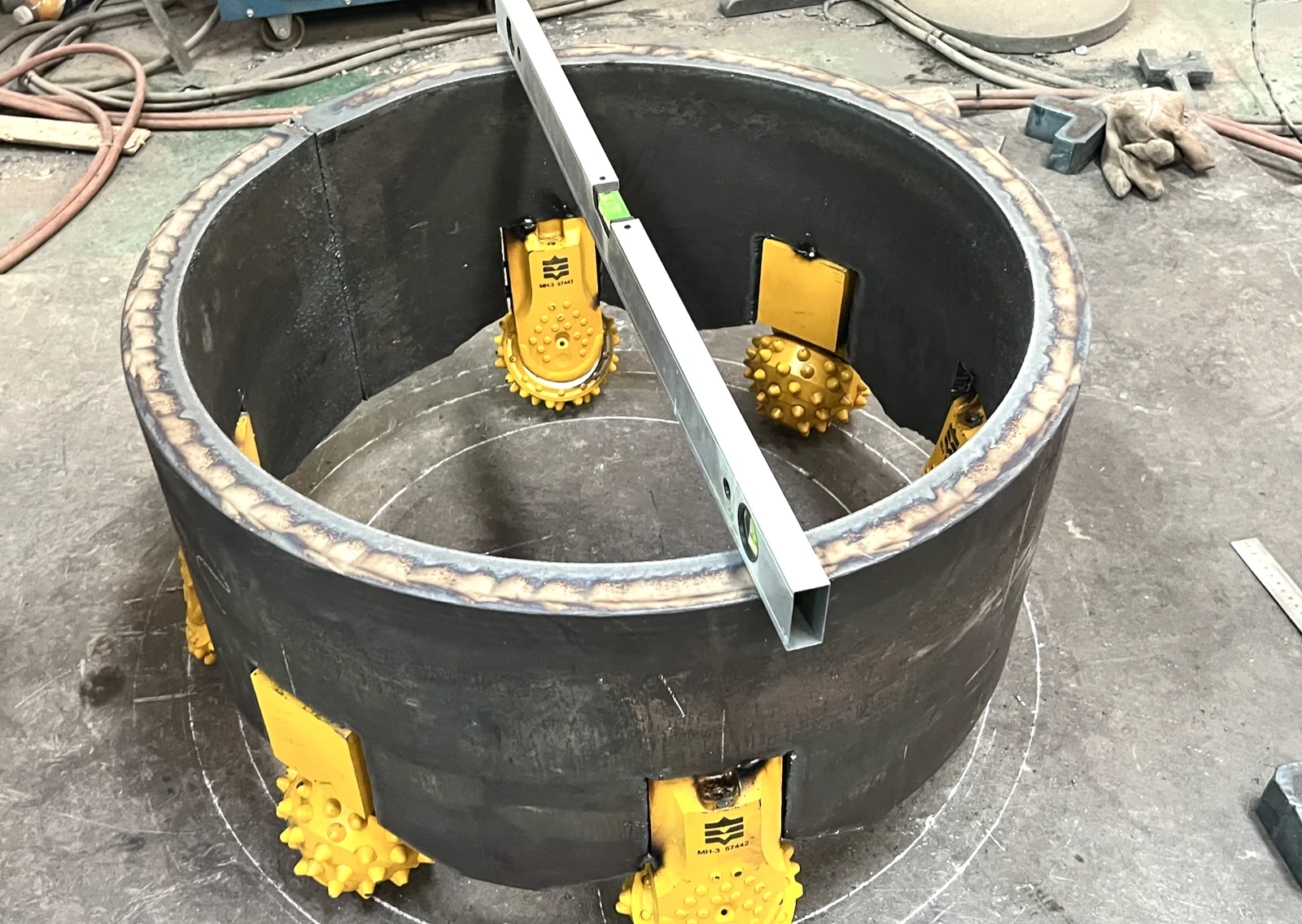
Before full welding, check each roller bit’s cutting path, projection and orientation against the barrel layout. The welding procedure must also protect the assembled bearing and seal. Correct positioning errors while the bits can still be adjusted.
01
Decide whether the existing ring can still locate the cutters
Clean the cutting ring and inspect it before removing the worn bits. Mark the condition of the openings, remaining wall, welds and guide strips. Measure diameters in several directions; a single tape reading can miss distortion. Retain photographs of each worn position so that the replacement work does not erase the evidence.
A fixture can repeat an error if it locates from a distorted ring or worn opening. Repair or replace that mounting structure first. Use a workshop setup if the site cannot provide a stable reference plane.
02
Control four dimensions separately
Use the selected roller-bit drawing and the barrel layout together. A preformed leg can simplify positioning, but it does not establish the correct installation on every ring.
| Control | What to check | What it prevents you from missing |
|---|---|---|
| Cutting radius | Inner and outer working points from one verified centre. | A correct steel-ring diameter with an incorrect cutting envelope. |
| Projection | Equivalent cutter points from a defined plane. | A bit that reaches the rock earlier than its intended neighbours. |
| Working angle | The leg’s specified reference faces and the selected layout. | An apparently seated leg installed at the wrong inclination. |
| Sideways orientation | Views across the leg and along the opening. | A twisted bit that passes a simple radius check. |
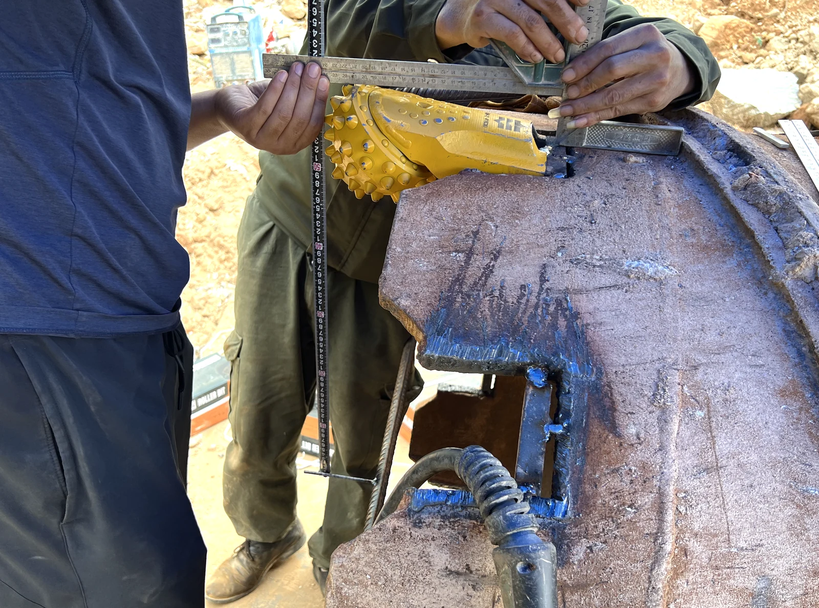
Compare equivalent points within each intended row. Inner and outer rows may have different design geometry. A matching radius does not establish projection or working angle.
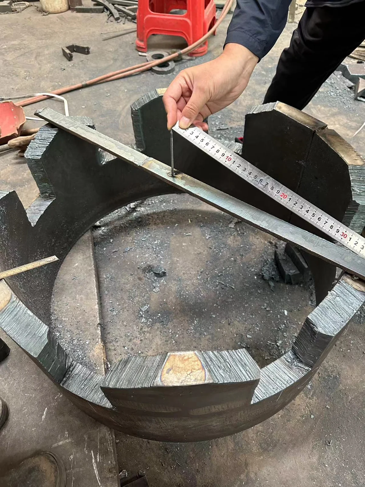
In the December 2023 workshop comparison, both a centre fixture and a marked steel-plate layout were used; cutter height needed a separate check. Recheck the centre after any contact or movement, then measure projection from the specified reference plane.
03
Tack the complete arrangement before welding it out
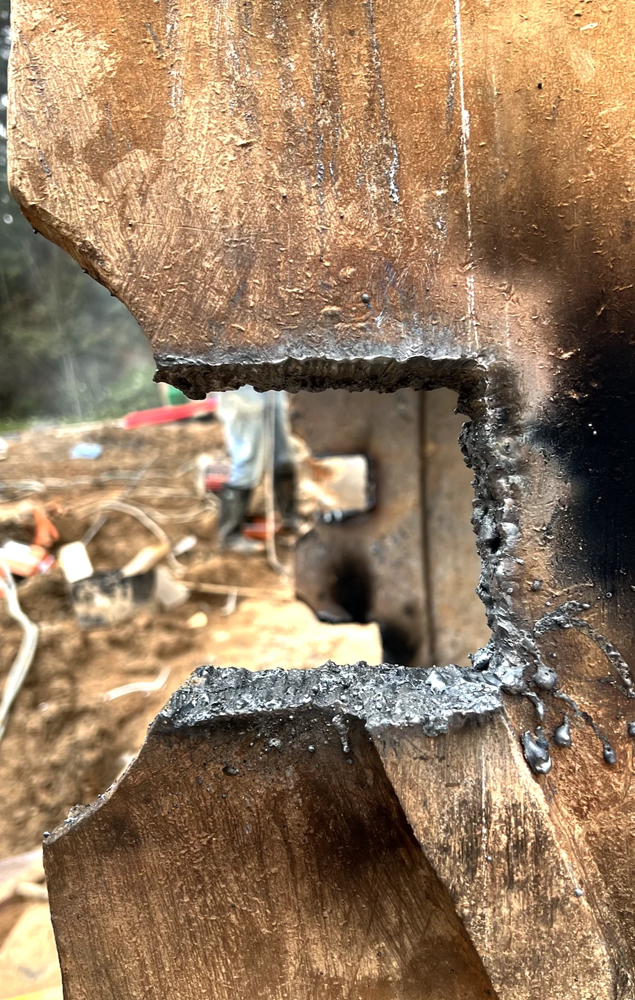
The photographed opening still has slag and uneven cut edges. Clear these before taking the final dimensions: a leg resting on a high spot can move as the weld is built. Compare the sound opening and seating faces with the replacement drawing. An oversized opening needs a suitable ring repair, not simply more weld.
Set the first inner and outer bits from the verified centre and plane, then work around the ring. Check the complete tack-welded set before full welding; do not use a different leg’s old outline as the positioning template.
Correct misplaced bits now. Record the accepted positions before moving the barrel for welding, then confirm that the tacks have held them.
04
Protect the assembled bit as well as the weld
The bearing, seal and lubricant are already inside the assembly. Heat reaching them must be controlled while the joint develops the required strength.
Plan balanced, distributed welding around the ring, allowing time between stages. Set the sequence, consumable, temperature limits, measurement points and cooling method for the actual materials and assembled bit before work starts.
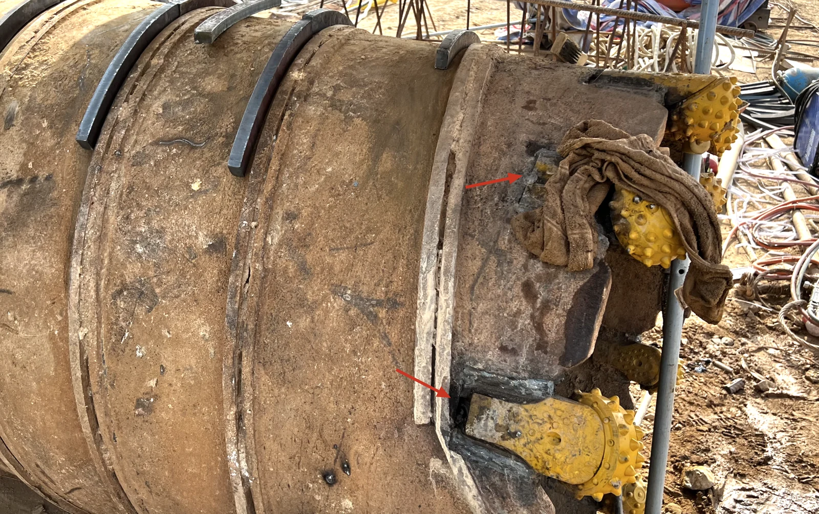
The photo locates the protection but does not specify a welding procedure or temperature limit. Follow the agreed temperature checks and protection method; pause if they cannot be maintained. Do not infer wet-cloth cooling or immersion instructions from the photo.
05
Release the whole cutting assembly
After welding and the specified cooling stage, repeat the geometry checks from the same references. Inspect the completed joints to the agreed welding acceptance requirements and check the roller bits for abnormal turning resistance, looseness or visible damage. A free-turning cone alone does not verify the internal condition of a heated assembly.
Hold the barrel out of service if a joint is suspect, a position falls outside its drawing limits, or a bit’s condition has changed during installation. Resolve the finding rather than adjusting the operating settings to compensate for an installation fault.