

 WS39 casing tooth
 JM cutter tooth
 B47K22 bullet tooth
Hunan highway project · Pre-rebuild survey
1,500 mm barrel rebuild: define the repair before fitting
DRILLNOVA · Field report · Updated
Three fractured legs and widespread insert breakage made this rebuild more than a cutter replacement. We surveyed all twelve positions, measured the retained ring and prepared a fitting approach for the next assembly. The result was a repair scope tied to the actual barrel, ready for the technical and purchasing discussion.
Start with the tool the customer needs to retain
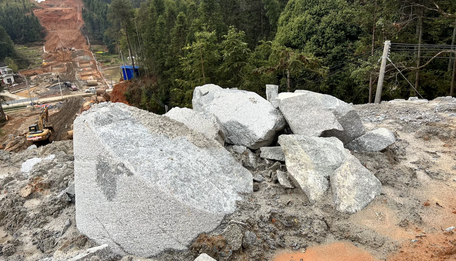
The Sany 405R worked on 1,800 mm piles using the nominal 1,500 mm barrel. The site note describes grey-white granite, moderately to slightly weathered, with many piles starting at or close to rock level. It quotes an average rock-socket length of about 10 m for the project.
For this application, our first task was to establish the condition of the retained opening, shell and cutter positions. The project’s average rock-socket length describes the work ahead; it does not measure how long the old roller bits had lasted.
What the twelve-position inspection found
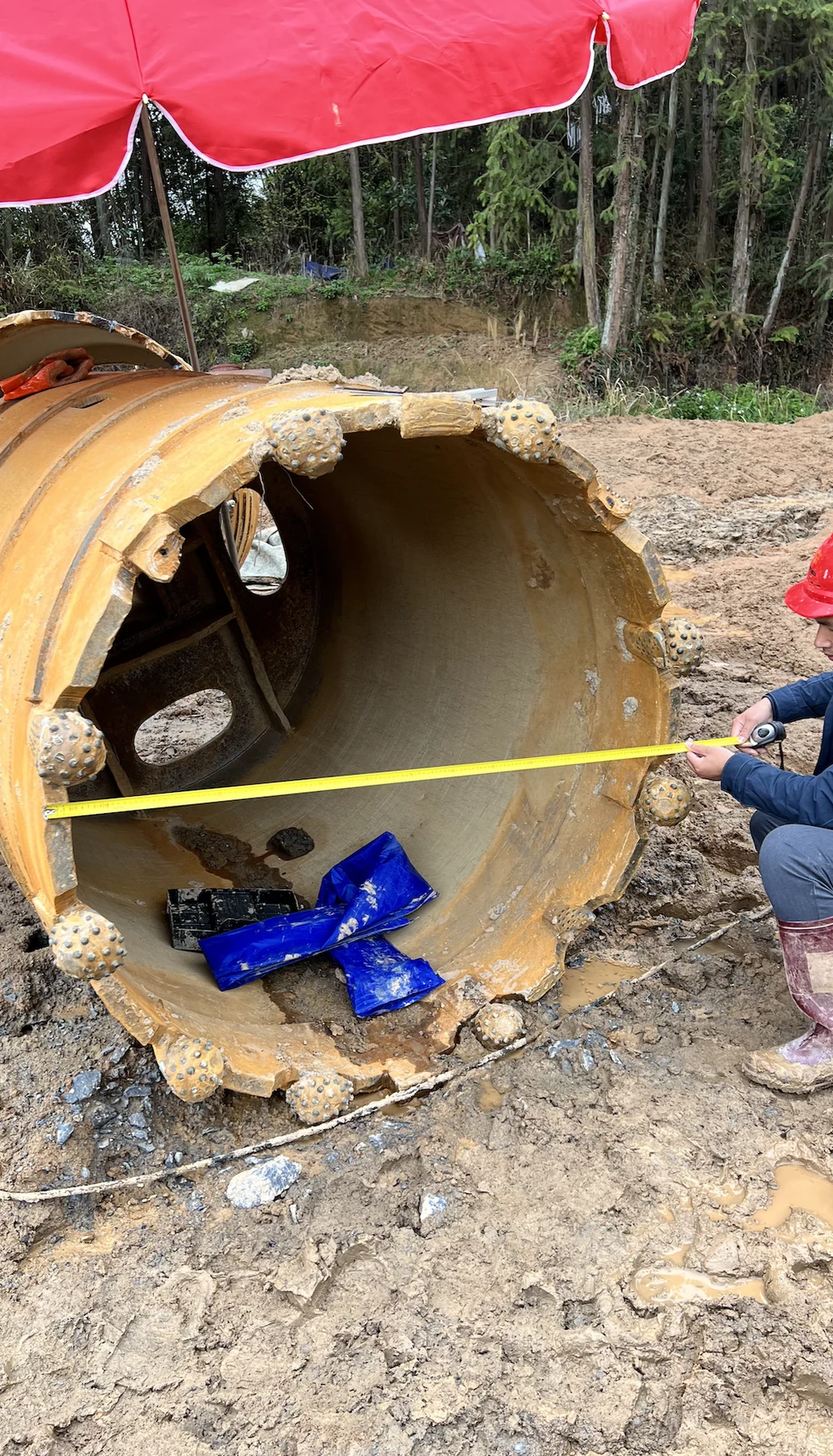
We recorded fractured legs at positions 2, 5 and 11, with varying insert breakage at the other positions. Numbering the photographs kept each finding tied to the actual cutter seat. It gave the replacement discussion a defined list of damaged positions, rather than a general description of a worn barrel.
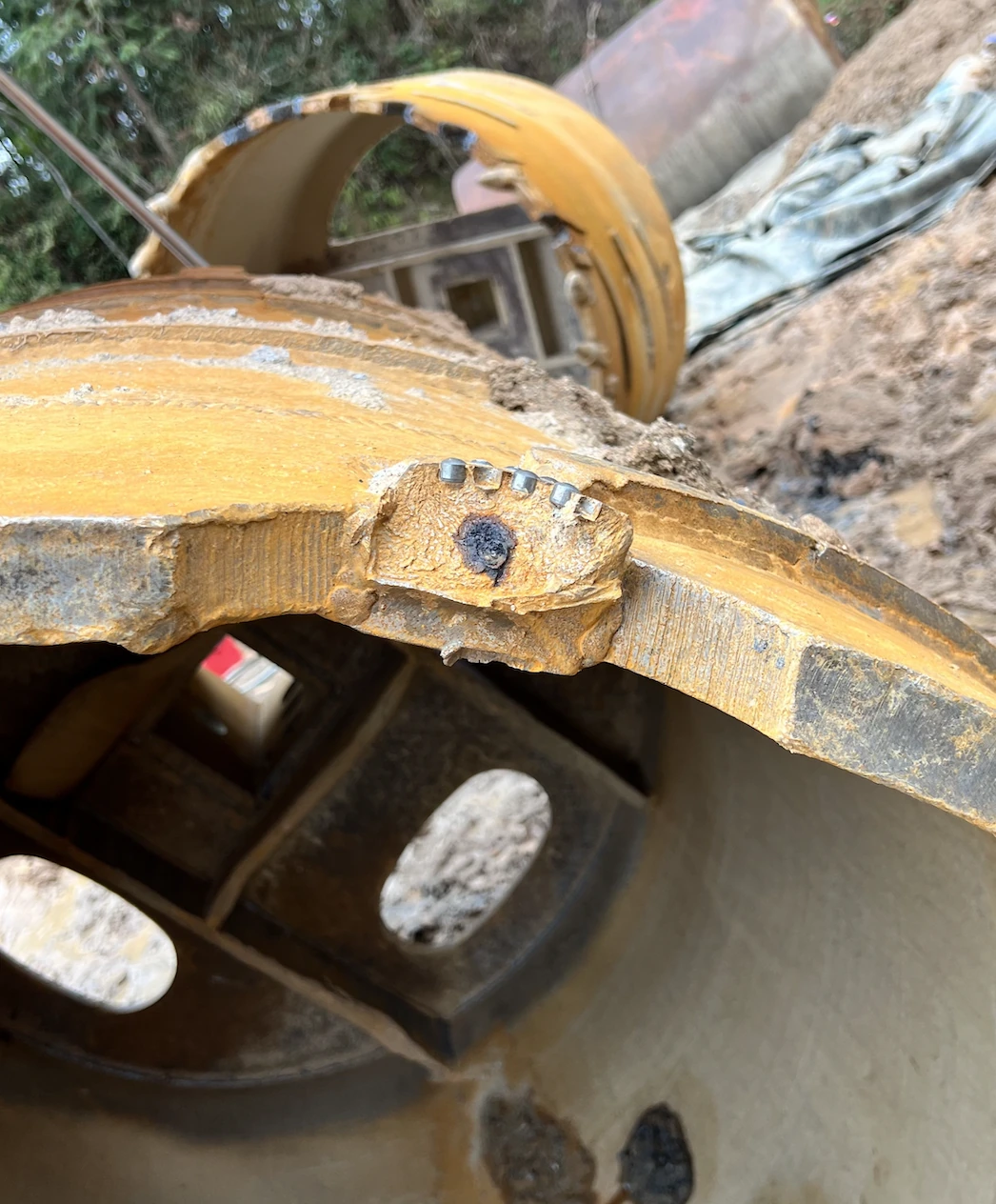
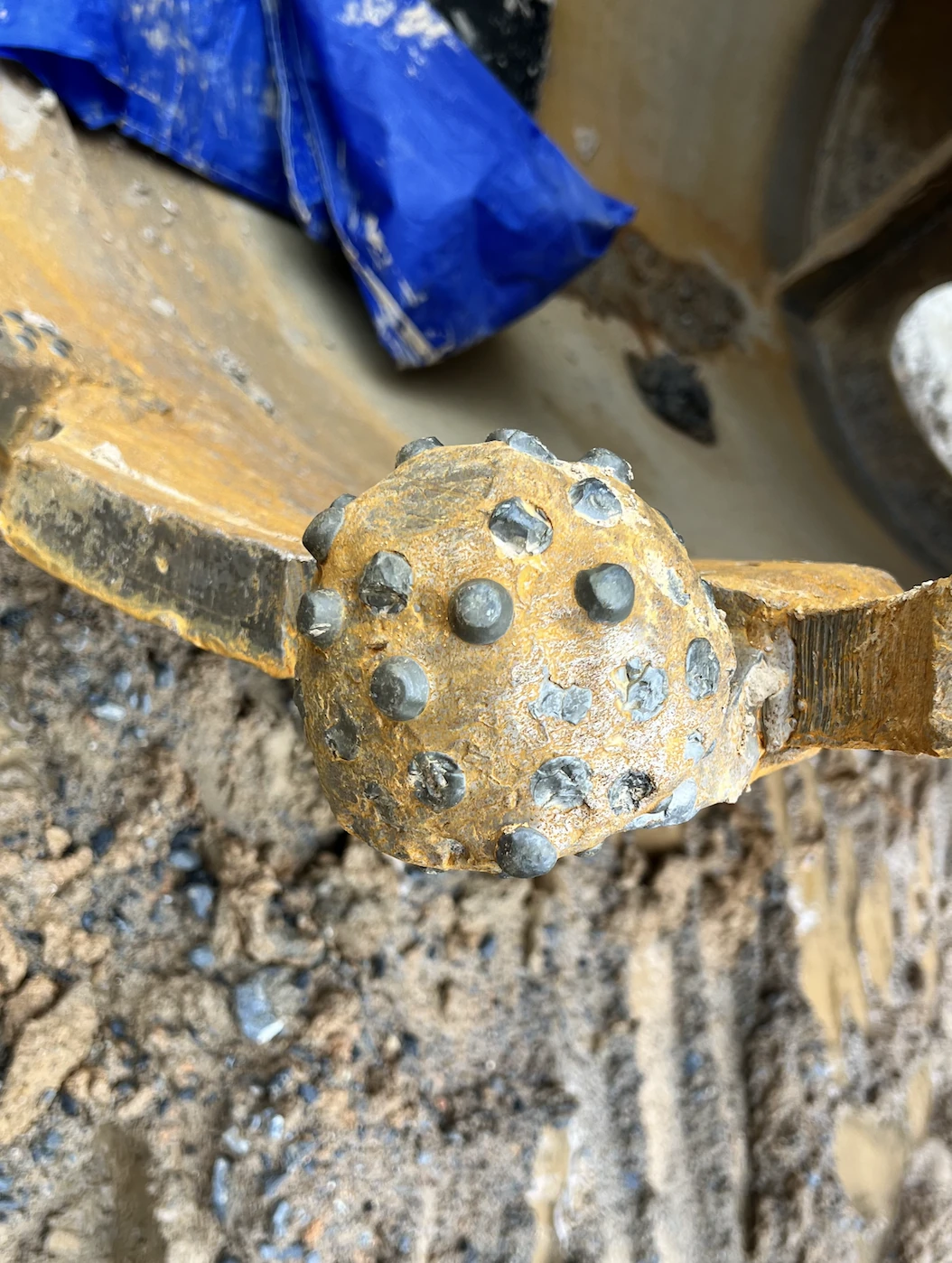
These are different cutter positions in the same pre-rebuild survey, not before-and-after performance photographs.
The measurements that changed the fitting plan
The existing ring measured 1,417 to 1,425 mm across the opening. This 8 mm spread describes the worn tool’s condition, not a fabrication tolerance. Replacement fitting needed those actual measurements.
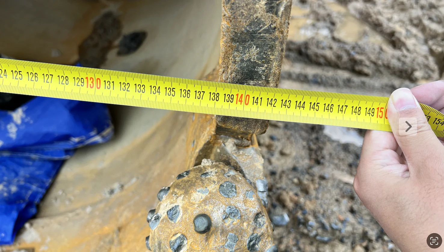
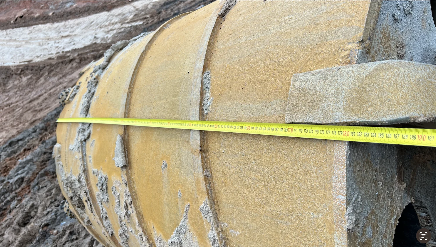
The 250 mm-long ring had a recorded 40 mm wall; three spiral guides measured 18–20 mm in height. Together with the cutter survey, these dimensions defined work on the ring, cutouts, scrapers and guides as well as the replacement roller bits.
Our proposed fitting approach
Establish one centre reference for the replacement layout. The measured maximum and minimum diameters informed the proposed centre-finding sequence, using a straight steel bar and a marked centre reference. The first inner and outer roller-bit positions would then be set and adjusted against that reference.
Prepare the seat and projection together
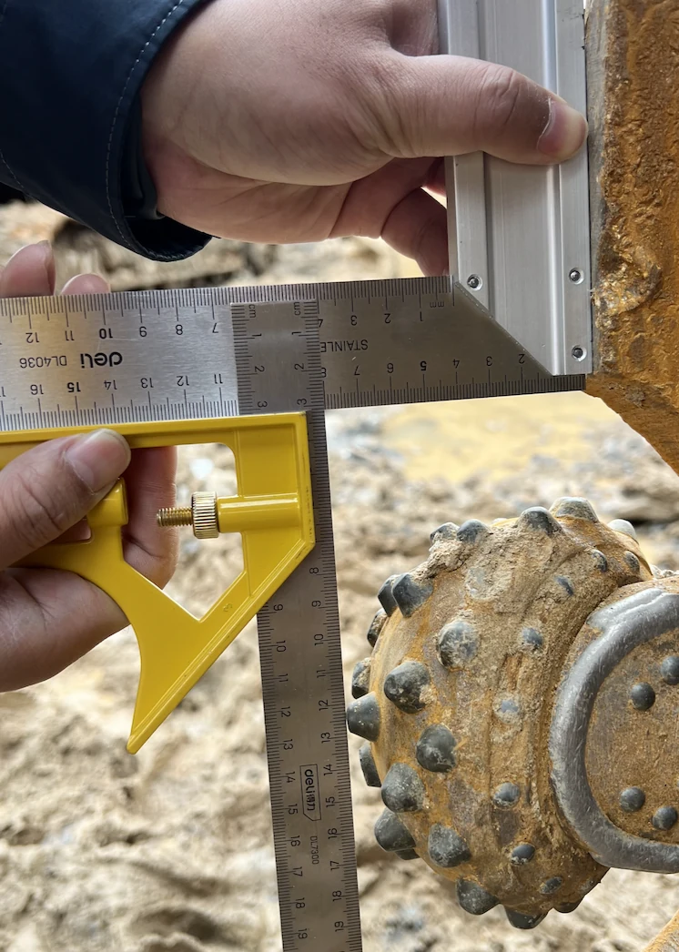
The old arrangement had a recorded embedment of 150 mm. We proposed spacers and a 130 mm embedment for the replacement arrangement, to be checked against the selected cutter drawing. The preparation sequence covered marking the cutouts, fitting the spacers, then checking the cutter’s cutting path, angle and projection before final welding.
Include clearance and scrapers in the rebuild
The proposal also called for reviewing the cutout size and considering two additional scraper blocks. Guide wear and the spaces around the roller bits belonged in the same preparation plan, so the replacement would be discussed as a complete lower assembly.
Measurement log: dimensions and all twelve positions
| Field | Original recorded scope |
|---|---|
| Average rock-socket length | About 10 m · project description |
| Pile-length notes | 10–20 m in the English note; 10 m to over 30 m in the Chinese note · ranges not reconciled |
| Rock description | Grey-white granite; moderately to slightly weathered in the Chinese note |
| Rock strength notation | “UCS 100 MPa+” in the site note · no laboratory test report supplied |
| Operating record | No numeric head-speed, feed-pressure or depth/time window attached to this survey |
| Item | Recorded measurement |
|---|---|
| Application / rig | G59 highway project; 1,800 mm piles; Sany 405R |
| Nominal core barrel | 1,500 mm |
| Cutting-ring measured diameter | 1,417–1,425 mm; 8 mm measured spread |
| Cutting ring length × wall thickness | 250 × 40 mm |
| Barrel shell length | 1,800 mm |
| Spirals | 3; recorded height 18–20 mm |
| Old cutter positions inspected | 12 individually numbered positions |
| Position | Recorded condition | Estimated insert breakage |
|---|---|---|
| 1 | Insert breakage | 45% |
| 2 | Fractured leg | — |
| 3 | Cone-body wear + insert breakage | 35% |
| 4 | Insert breakage | 90% |
| 5 | Fractured leg | — |
| 6 | Insert breakage | 70% |
| 7 | Insert breakage | 20% |
| 8 | Insert breakage | 90% |
| 9 | Insert breakage | 20% |
| 10 | Insert breakage | 80% |
| 11 | Fractured leg | — |
| 12 | Insert breakage | 90% |
Insert-breakage percentages are the survey’s visual estimates. The three fractured-leg positions are recorded separately. Project pile depths and rock-socket lengths are not metres drilled by this set.
Proposed workshop preparation
| Survey finding | Proposed work | Item to confirm before fitting |
|---|---|---|
| Cutting ring varies across measurements | Use maximum/minimum measurements to establish a shared centre | Reference the cutter layout to the agreed barrel centre |
| Old embedment recorded as 150 mm | Use spacers for a proposed 130 mm embedment | Check that case-specific proposal against the replacement drawing |
| Extensive broken inserts and 3 fractured legs | Review ground transitions, cutter placement and operating records | Keep position-specific findings; no single cause was established |
| Guide wear and clearing concerns | Prepare cutouts and consider 2 additional scraper blocks | Confirm cutout size, scraper clearance and welding plan |
This is the survey-stage scope, not a record that the rebuild was completed. No single cause of the damaged legs and inserts was established.