

 WS39 casing tooth
 JM cutter tooth
 B47K22 bullet tooth
DRILLNOVA / ROTARY DRILLING TOOLS
Roller-bit core barrels
The roller bits, cutting ring and core-recovery sequence form one system. Review a complete barrel, a replacement lower assembly or a conversion using the installed cutting paths.
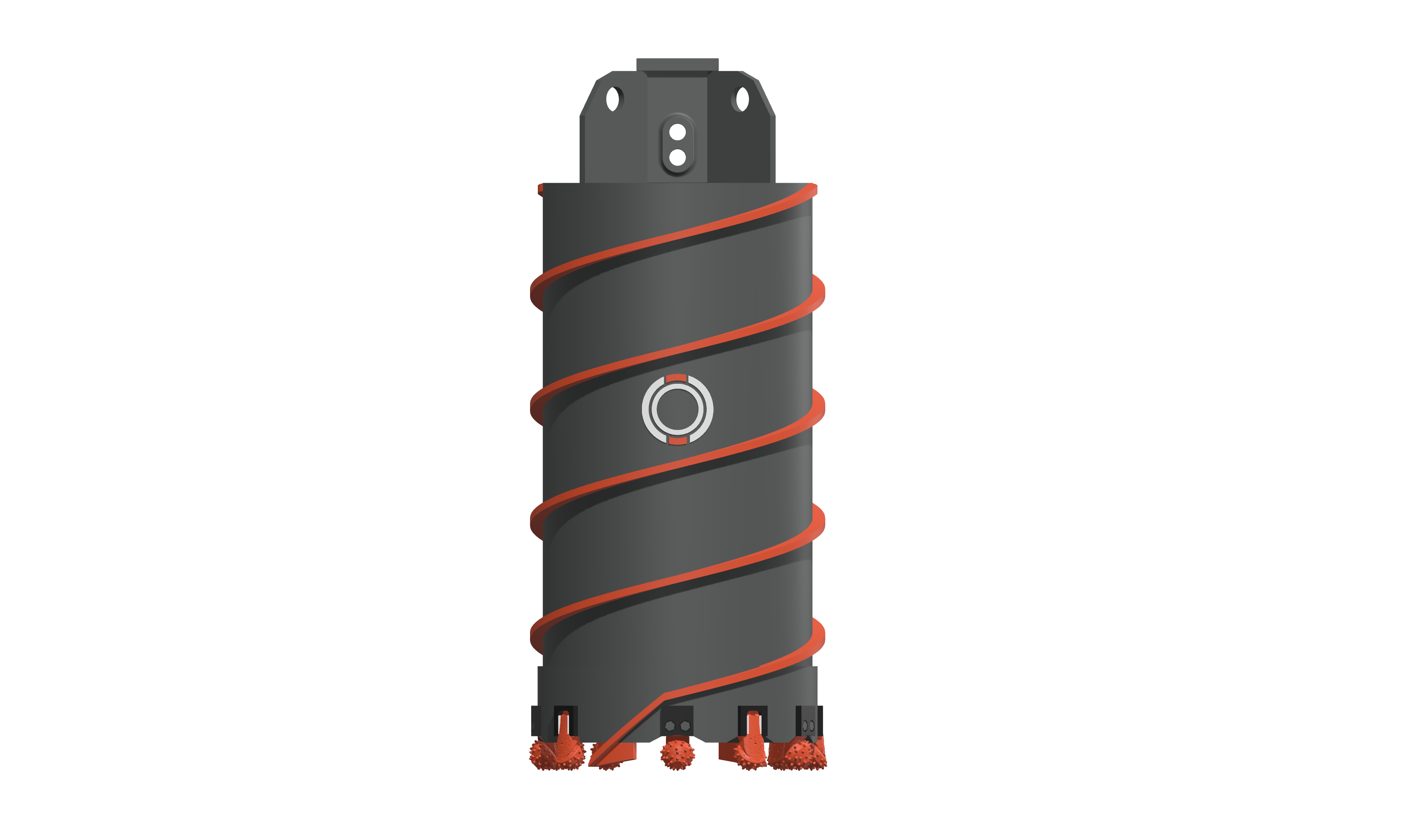
Build the cutting ring around the working paths
A roller-bit core barrel cuts an annular groove around the rock core. Its working geometry comes from the installed cutters: the supporting steel ring, the outer cutting path and the inner cutting path are three different references. Changing a roller-bit model or its position can change that geometry even when the barrel body stays the same.
Review the first inner and outer cutters from a common centre and reference plane. Radial position sets the cutting path; leg tilt, sideways orientation and projection determine where the working inserts sit. Check equivalent positions around the complete ring, rather than accepting each leg in isolation.
| Configuration | What changes | Assembly decision |
|---|---|---|
| Complete new barrel | Shell, cutting ring, cutter arrangement, guides and drive connection form one specified assembly. | Establish the cutting envelope and working height with the complete tool. |
| Replacement lower assembly | A new cutting ring must connect to retained steelwork. | Check the joining reference, remaining body condition and guide arrangement. |
| Cutter replacement or conversion | New legs occupy existing or modified openings. | Inspect ring shape, opening fit and projection before copying the old positions. |
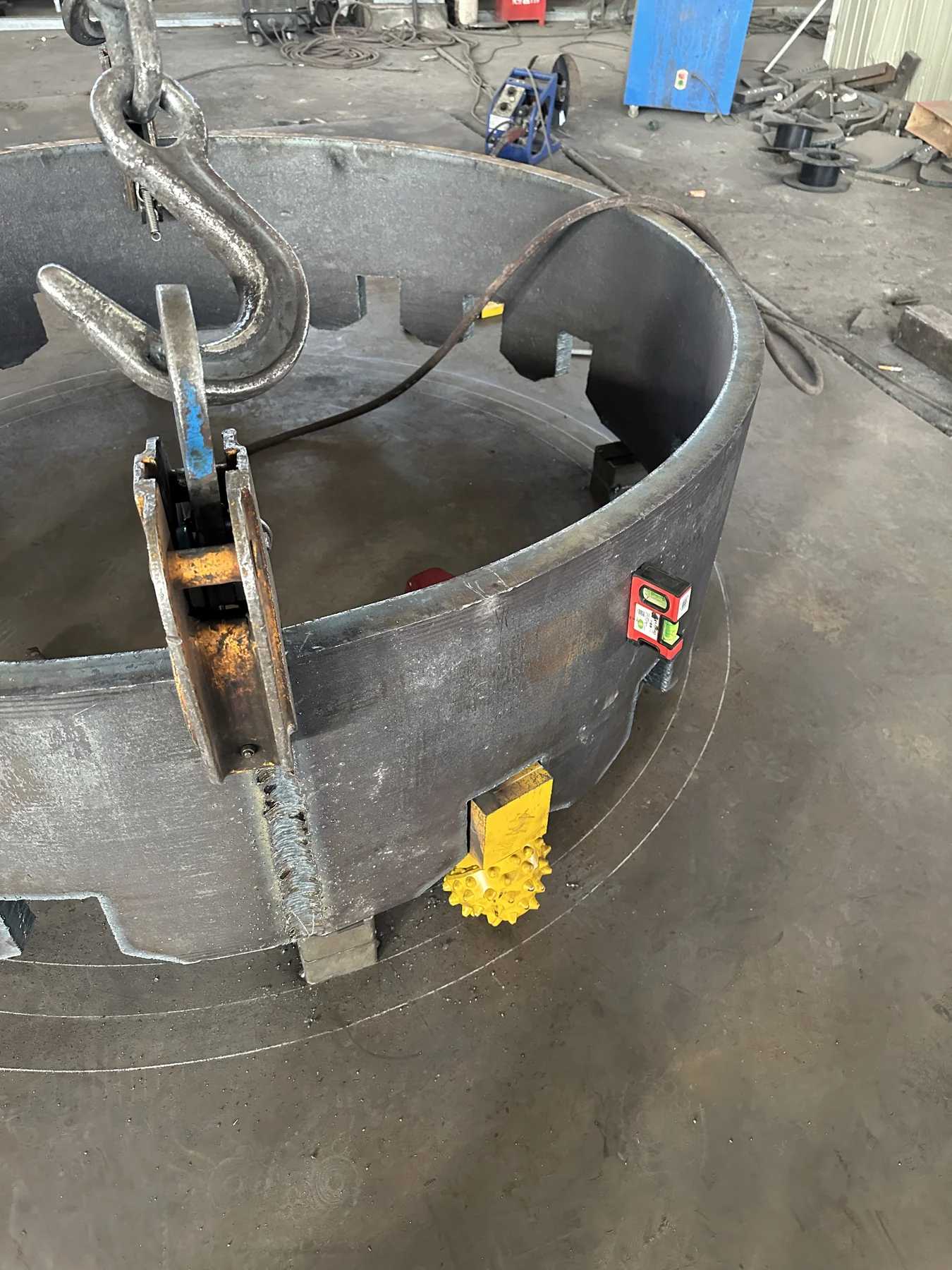
Position first, remeasure the full set
The 1,800 mm build used 16 roller bits and four scrapers. Its 1,770 mm outer and 1,530 mm inner cutting paths defined a 120 mm radial groove width. The separate steel-ring reference was 1,650 mm.
After locating the first inner and outer bits, the workshop positioned the remaining set, remeasured it and adjusted individual cutters. This is a practical inspection sequence: retain the design value, actual reading and any correction at each position. Final geometry should also be checked after welding, using the procedure and heat controls specified for the assembly.
These dimensions describe one recorded build. They are not a standard configuration for every barrel carrying the same nominal size.
Include the surrounding assembly
Scrapers, external guides and the core-recovery sequence belong in the review alongside the cutters. For a rebuild, photographs around the whole ring reveal whether the enquiry concerns new roller bits alone or additional steelwork. State the intended supply scope and current tool condition so the quotation covers the work actually required.
CUTTING ARRANGEMENT
See how the parts are arranged.
See the roller-bit assembly in motion.
Read the video description
The view moves from the complete barrel above the rock to a transparent body and the roller bits around the cutting ring.
The animation shows the cutting arrangement around a roller-bit core barrel. Mounting geometry varies with the barrel design.
Before reviewing a barrel requirement
What should I include in a roller-bit or core-barrel enquiry?
State whether you need individual roller bits, a replacement set or a complete core barrel. Include the model or clear photos, tool diameter, mounting details, quantity and intended formation. For an existing assembly, add dimensions and connection photos so the requirement can be reviewed before a quotation is prepared.
Why can a short barrel recover a longer rock core?
Core drilling and recovery can involve different tools. A short recovery barrel may break and lift rock prepared during an earlier drilling stage. Identify the tool’s function before comparing its length with the recovered core. For selection support, provide the hole diameter, core dimensions and the drilling and recovery tools already in use.
What information is needed before discussing pressure or rotation speed?
Send the rig model, tool diameter and configuration, roller-bit model and arrangement, formation, drilling depth and available operating records. Include photos of the controls and explain what each reading represents. These details support a review of your setup; a value from another video should not be treated as a setting for your equipment.
PRODUCT & PROJECT ENQUIRY
Review a roller-bit barrel requirement
Send the required barrel size, drive connection, ground conditions and photographs around the existing cutting ring. State whether you need a complete barrel, a replacement lower assembly or cutter replacement.