

 WS39 casing tooth
 JM cutter tooth
 B47K22 bullet tooth
The January 2024 build used shared layout references to position 16 roller bits, establish the first inner and outer cutters, and recheck the full arrangement. The recorded dimensions below describe this 1,800 mm application, not a standard layout for every barrel.
How were the first inner and outer positions established?
The workshop placed the cutting ring against common references and used the first inner and outer roller bits to establish the arrangement. The outer cutting path, steel-ring reference and inner cutting path remained separate.
Confirm radial position together with the leg angle and sideways orientation. Locating each leg independently against the nearest shell edge would not reproduce the same common reference.
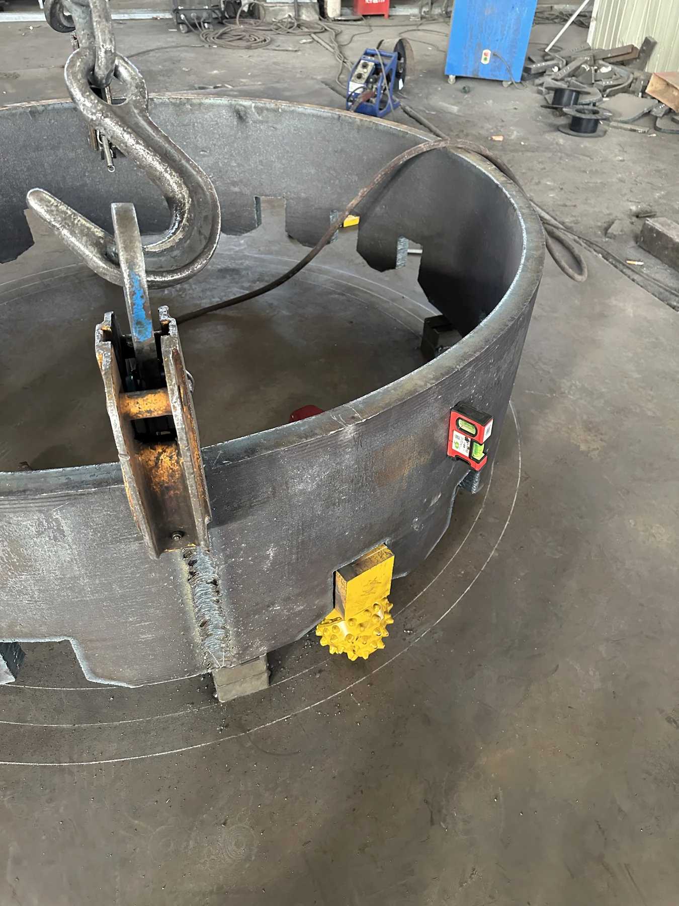
Was cutter level checked after initial positioning?
The record shows a spirit level used during the leg-position check. Once the initial arrangement was in place, the workshop remeasured the full set and adjusted positions where necessary.
Record target and measured cutter positions against the selected reference surfaces. Keep the level check with the corresponding position measurement.
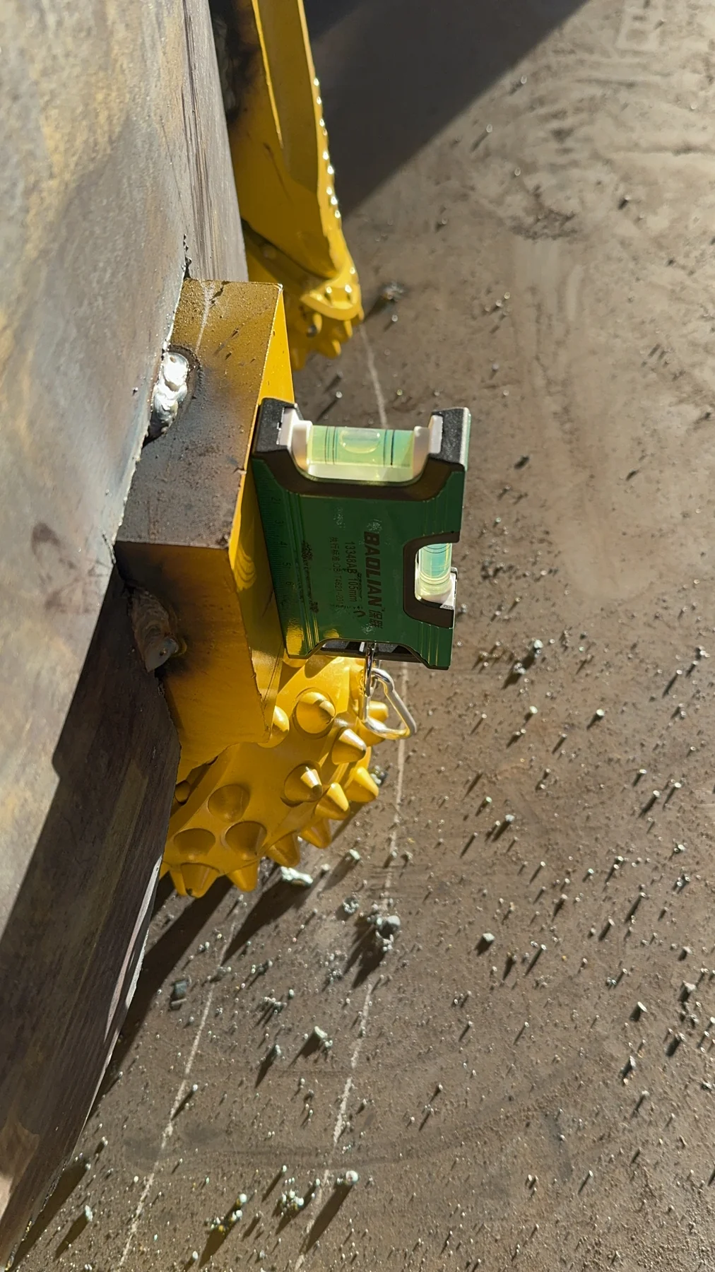
Was the complete cutting assembly reviewed?
The documented arrangement included the roller bits, four scrapers and external spoil guides. Review their relative positions as a complete assembly after the cutter layout is established.
Use the finished assembly record to connect each component to the drawing. The photographs document workshop positioning and assembly, not an operating trial.
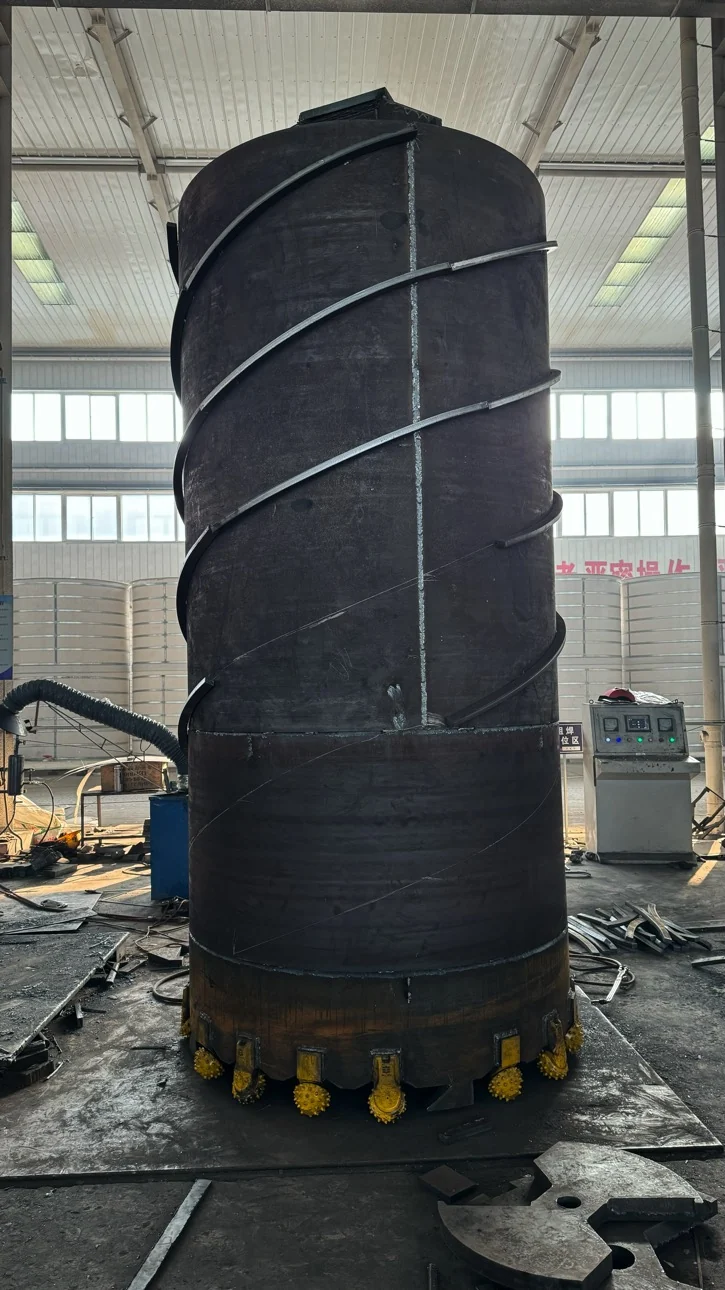
From layout to fit-up
Look at the working points together
Two more views from the January 2024 build connect the layout to the fitted components. The first helps locate the cutter; the second brings the scraper into the assembly check.
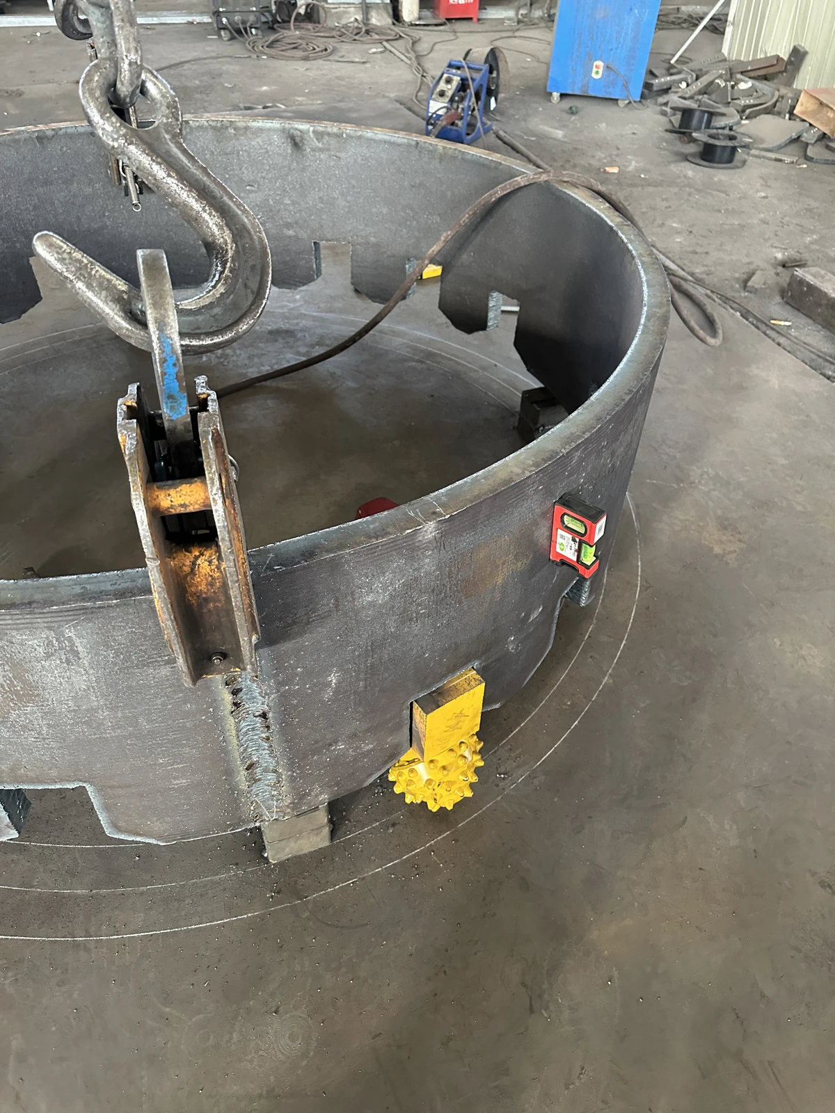
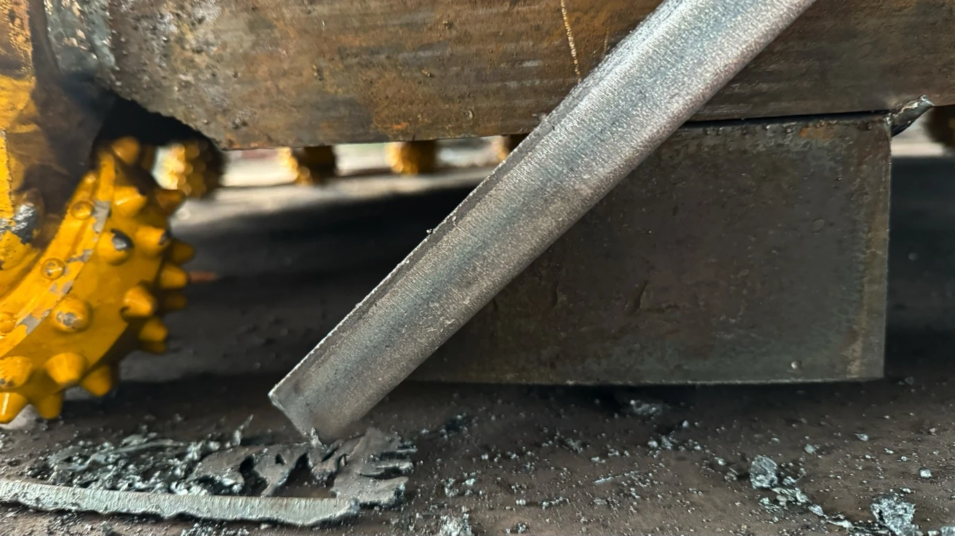
Keep the drawing reference and measured position beside the close-up. This makes a fitting review useful for the workshop and prevents an overall assembly photo from standing in for a dimensional check.
What needs a hold point before final welding?
The build record specifies 16 roller bits and four scrapers. It also gives a 15 mm height difference between scraper and roller-bit references. Establish which component is higher from the selected drawing before setting that difference; an unsigned distance does not define the direction.
| Hold point | Check to complete | What a missed check can leave behind |
|---|---|---|
| First inner/outer pair | Outer working radius 885 mm; inner working radius 765 mm; projection and orientation from the drawing. | A wrong first pair becomes the reference copied into later positions. |
| Complete tack-positioned set | Confirm all 16 bit positions and four scraper positions, the 1,770 / 1,530 mm working paths and the specified scraper-height relationship. | Finishing welds early can lock in one high cutter, an incorrect scraper level or a twisted leg. |
| After controlled welding and cooling | Repeat the same geometry checks, inspect the welds and compare cone movement with the pre-weld condition. | Weld shrinkage or a changed assembly condition may otherwise appear only during the first run. |
The 15 mm relationship belongs to this build. Use the working drawing for its direction, measuring points and tolerance; it is not a general scraper setting for other diameters or cutter layouts.