

 WS39 casing tooth
 JM cutter tooth
 B47K22 bullet tooth
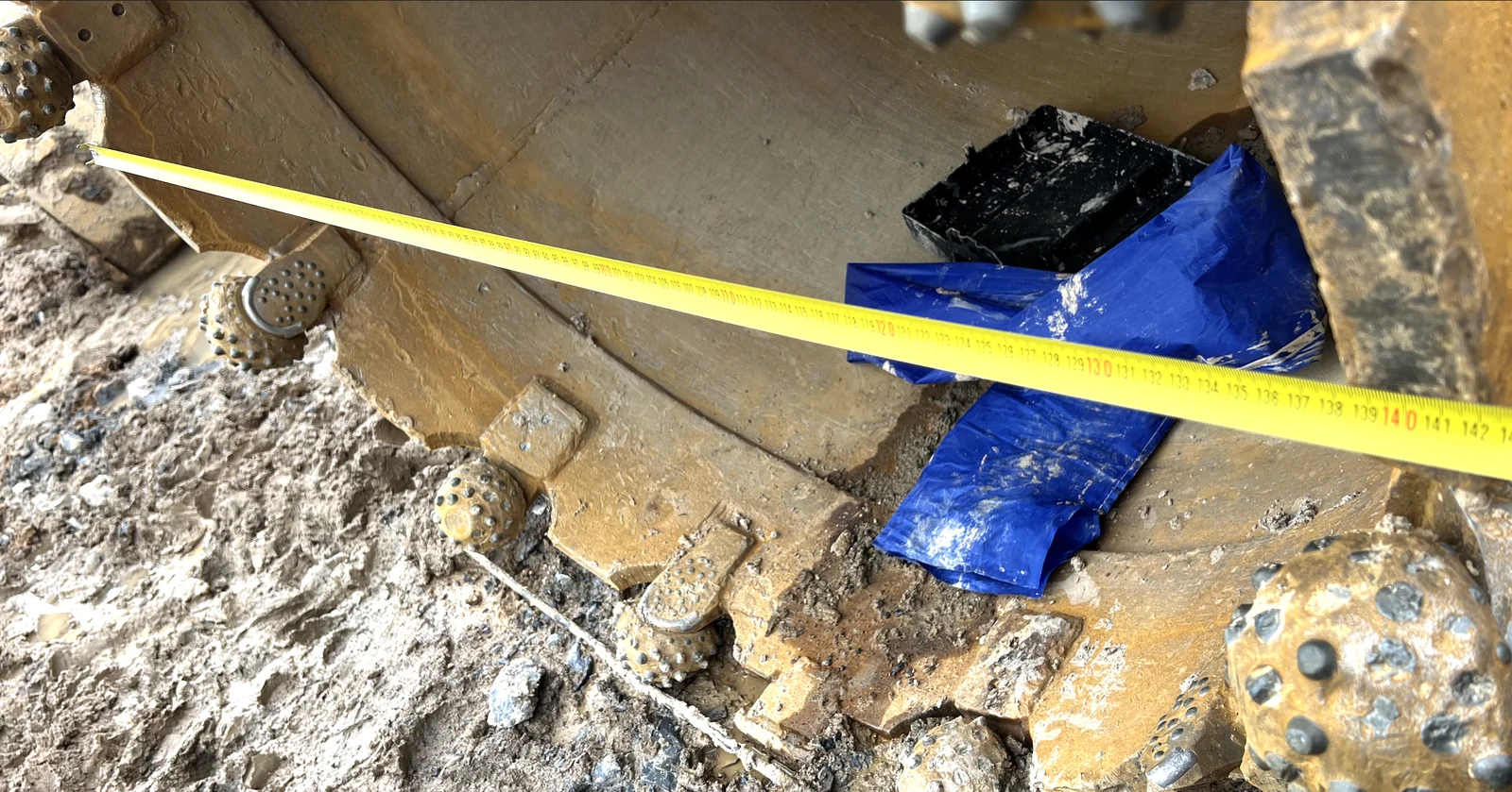
Before fitting new roller bits, inspect the cutting ring for distortion, worn openings and damaged guides. The mounting base may need repair before cutter replacement.
Is the ring geometry suitable for the intended rebuild?
Inspect the ring, welds and worn areas. Measure diameters in marked directions to reveal distortion, then compare with the selected drawing and acceptance limits.
Do not treat one tape measurement as proof of roundness. If the ring cannot provide the required reference, resolve repair or replacement before positioning new roller bits.
See the measured 1,500 mm barrel survey: ring dimensions, cutter damage and a proposed fitting plan.
Will the new leg seat in the old opening?
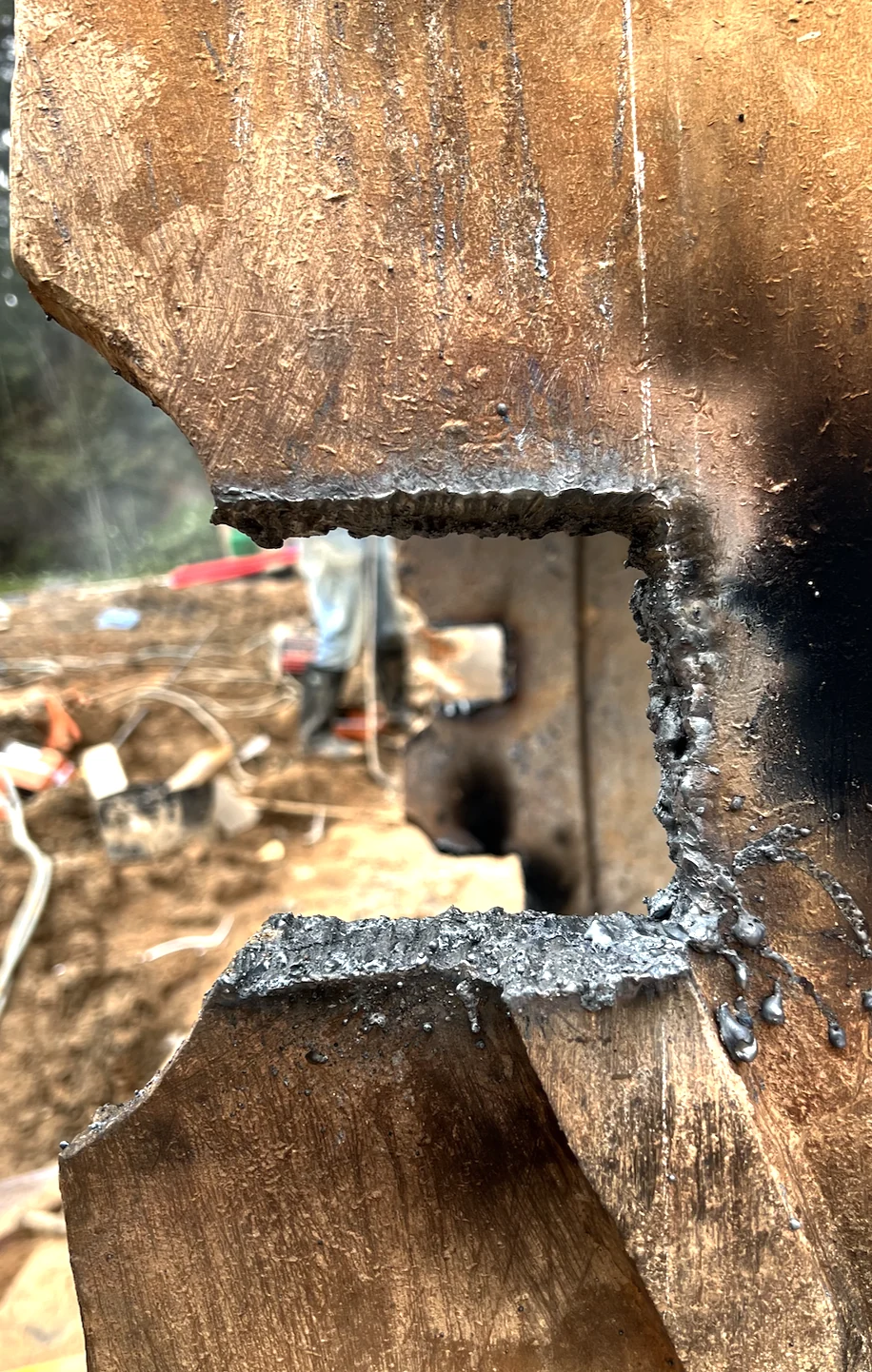
Remove slag and burrs so that the seating and opening can be assessed. Measure opening width and depth against the new leg and the required position.
An opening enlarged by the previous installation or removal may not support the intended fit. Record the repair decision and final seating geometry rather than forcing the new part into the old outline.
Are the guides and companion cutting path still suitable?
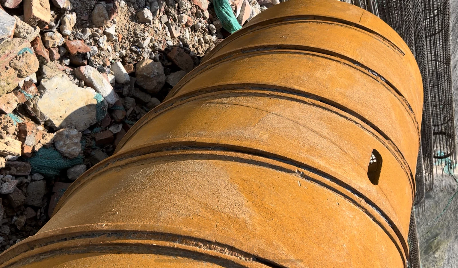
Inspect the external spoil guides and record remaining dimensions and damage. Review their position with the cutters and any companion core-removal tool.
Confirm the actual maximum cutting diameter and annular groove width. Nominal pile diameter alone does not establish clearance or show whether the complete repaired arrangement matches the intended work.
Follow the 1,200 mm MH-3 site refit: the shell was reused, then later inspections compared both barrels’ cutting paths and tracked wear.
From the repair record
An old barrel, from survey to fitting
A site record for a barrel described as 1,400 × 2,000 mm followed the retained shell through inspection and rebuilding. Worn guide strips and the absence of scrapers were included in the repair scope, alongside a proposed set of twelve roller bits and three scrapers.
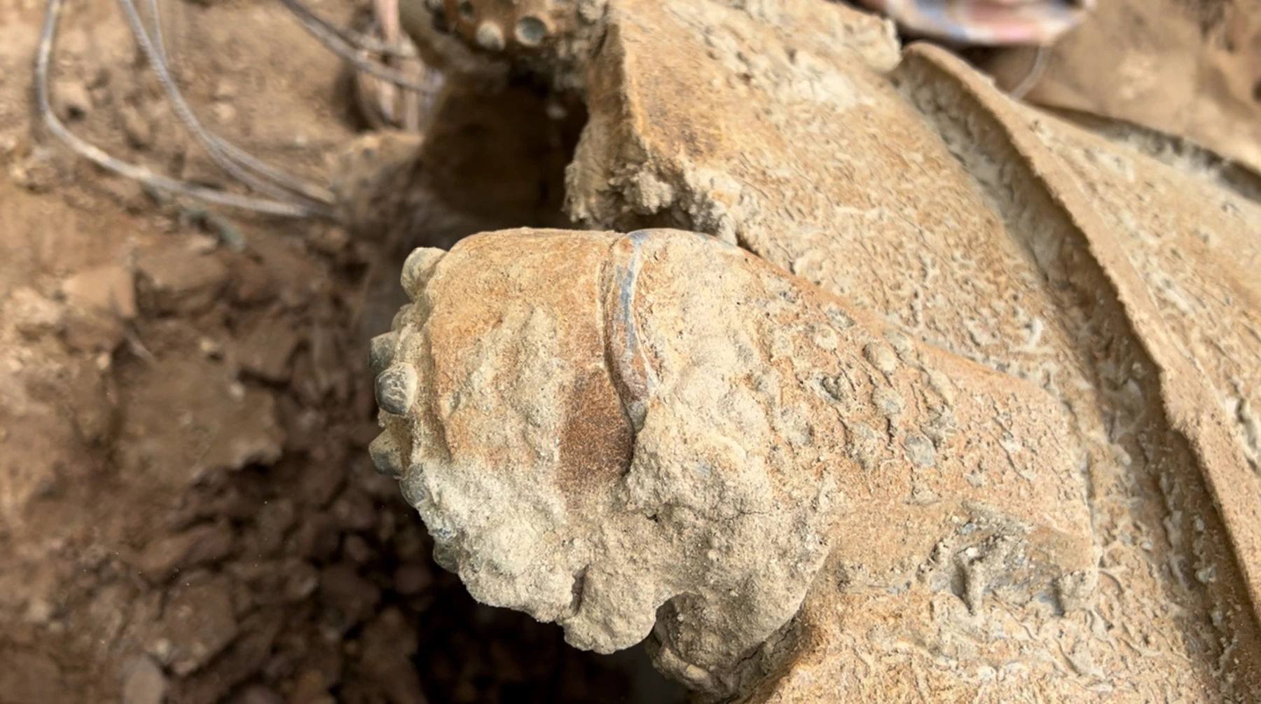
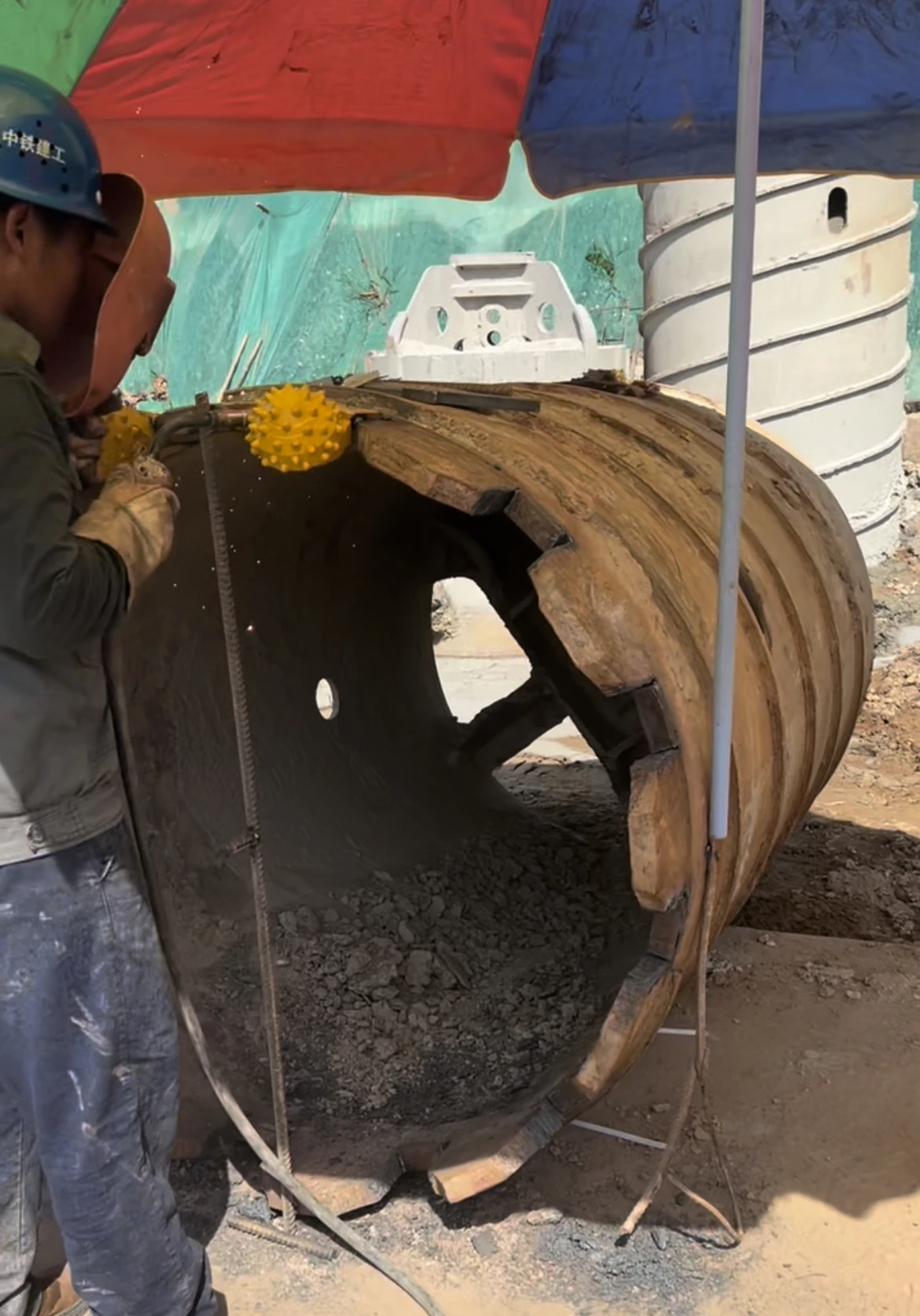

What was measured and checked during this rebuild?
| Item | Recorded condition or decision |
|---|---|
| Guide strips | Remaining height: 15–20 mm. The record used 30 mm as its reference and included guide restoration in the review. |
| Cutting-ring diameter | About 1,296 mm against a stated 1,300 mm reference. The notes considered wear or manufacturing variation; this is not an acceptance tolerance. |
| Opening and embedment | The notes give an existing 170 mm opening depth, an early 130 mm recommendation and a later 140 mm embedment proposal. These belong to different stages; none should be copied as the final fitting dimension without the agreed drawing and finished measurements. |
| Cutting path | The proposal reduced the annular groove width from 120 to 118 mm. No timed drilling comparison was supplied to verify the expected effect. |
The documented work sequence: clean the ring and cut-outs; confirm the openings, spacer thickness and cutter projection; establish the centre; position the first inner and outer roller bits; check the maximum and minimum cutting diameters, projection, axial offset and angle before completing the welds and scraper fitting.
The finished photographs document assembly. They do not establish the final dimensional acceptance, subsequent metres drilled or service life. The record dates the site work to 24 August without stating the year.
New roller bits, ring repair or a replacement lower assembly?
Inspect the retained steelwork before choosing the supply scope. Review the actual tool and drawing; nominal diameter alone cannot decide it.
| Scope to discuss | When it may fit | What defines the quotation |
|---|---|---|
| Replacement roller bits | The ring, openings and reference geometry remain suitable after inspection. | Affected cutter positions, mounting details and the parts required. See an individual replacement inspection. |
| Ring repair and new roller bits | Inspection confirms the retained ring can be repaired to the agreed mounting and geometry requirements. | Measured condition, repair drawing and procedure, and checks before fitting. |
| Replacement cutting ring or lower assembly | The existing ring cannot be restored to the agreed requirements, or a conversion needs a different arrangement. | Connection to the retained shell, cutter layout, cutting paths and included components. |
If the shell or drive connection is also unsuitable, include the complete barrel in the review. The agreed scope should identify what is retained, repaired and supplied new.
Prepare the old cutting ring in the right order
| Order | Work to finish | Symptom if it is skipped |
|---|---|---|
| 1. Clean and survey | Clean the ring and old mounting area; measure its shape and identify the least-worn usable reference. | Packed material or worn edges become false measuring datums. |
| 2. Mark the common baseline | Mark the selected cut height and the new leg opening profile before removing the old parts. | Each old opening is copied separately, leaving inconsistent opening depths. |
| 3. Remove old parts and dress the opening | Remove the old bit and weld by the selected repair method; remove slag and burrs and expose the seating surfaces. | A high spot prevents the new leg seating even when the opening looks wide enough. |
| 4. Dry-fit before tacking | Compare the actual opening with the new leg profile and inspect surrounding ring material. | An oversized old cut-out leaves a gap the new installation weld was not designed to bridge. |
| 5. Restore the reference and tack | Establish the centre and plane, position the first inner/outer pair, then measure the full tack-positioned set. | Using an old weld face as the reference reproduces the earlier misalignment. |
If the ring is cracked, materially thinned, distorted or cut too wide, define a ring repair or replacement before fitting the bits. Do not use miscellaneous steel or rebar to fill a gap without an engineered joint and repair procedure.