

 WS39 casing tooth
 JM cutter tooth
 B47K22 bullet tooth
Use a verified centre to compare cutter radii, and a defined plane to check projection and orientation. A December 2023 workshop record compared a centre fixture with a marked steel-plate layout; both still required checks of the complete cutting arrangement.
Is the centre reference stable and repeatable?
The workshop established a centre on cross-members and checked distances towards the ring and its openings. The record also noted that actual fabricated-ring dimensions differed from the requested sizes.
Record the reference centre and plane before locating the first inner and outer roller bits. Check opening depth, radial position, angle and sideways orientation instead of repeating a measurement from a worn or irregular edge.
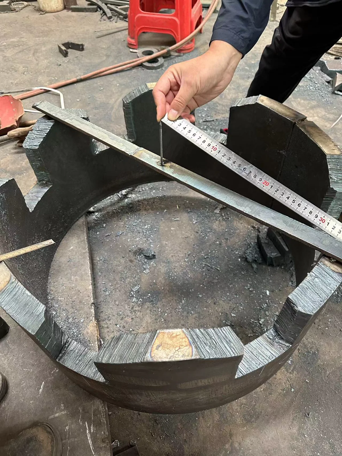
Does the complete arrangement agree with the layout plate?
The comparison method used concentric references on a flat steel plate and squares to check the ring and cutter projections against those lines. Recheck the full set after the initial inner and outer positions have been established.
Check cutter height separately. In this record the centre-fixture approach was described as slightly less precise in the comparison; that observation does not set a universal tolerance or select a method for every fabrication.
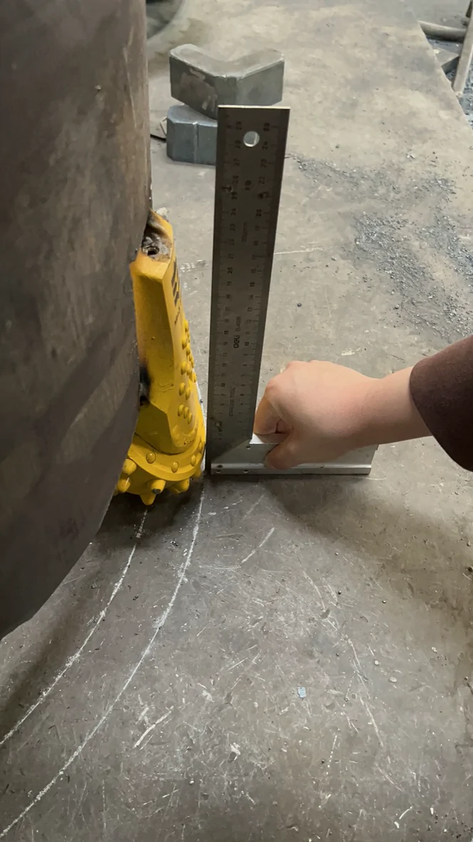
Check the centre before the cutters.
Watch the tape move between measuring positions on the cutting ring. A shared centre gives the workshop one reference for the cutter layout.
What the video shows
A worker holds a tape at the centre fixture and checks distances towards the ring and its openings. The clip shows the measurement method; the readings are not legible enough to establish a tolerance.
Use the shared centre reference to check cutter positions against the assembly drawing.
Open video fileAt the measurement points
Three checks before locating a roller bit
These additional photographs come from the same December 2023 workshop record. Follow the reference from the ring to the pin, then check the cut-out depth before using it to position a leg.
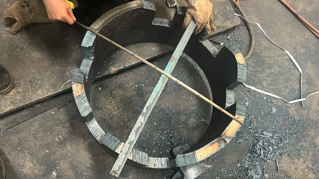
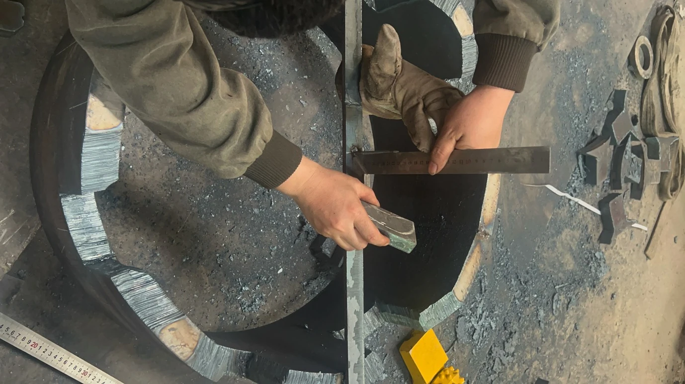
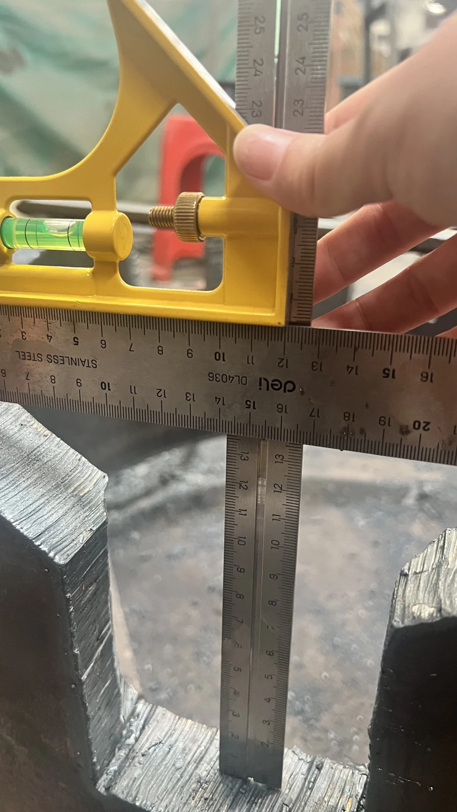
Record the centre, reference face and opening number with each measurement. The photos show the checking method; use the selected drawing for the required dimensions and tolerances.
What must be rechecked when the barrel or fixture moves?
The workshop recorded actual ring diameters of 803–805 mm for an 800 mm request and 905–906 mm for a 900 mm request. A nominal radius therefore did not describe every point on the fabricated ring. Establish the actual ring condition before transferring a cutter layout.
| Event | Possible error | Repeatable check |
|---|---|---|
| Before the first cutter | The centre is placed from an irregular or worn edge. | Compare opposite directions and several ring positions, identify the selected datum and verify the centre against the intended layout. |
| After adding the centre pin | The pin leans even though its base is centred. | Use a square in more than one direction; remeasure from the pin’s working tip, which is the point used to locate cutters. |
| After rolling or repositioning the barrel | The pin or cross-member is bumped. | Repeat the original reference measurements before copying more cutter positions. Do not reset only the next cutter around a moved centre. |
| After tack positioning | Correct radii hide unequal projection or sideways twist. | Use the reference plane and square to compare height and orientation independently of the radius measurement. |
The reported diameter ranges describe these fabricated rings. They are not an allowable ovality or a new production tolerance.