

 WS39 casing tooth
 JM cutter tooth
 B47K22 bullet tooth
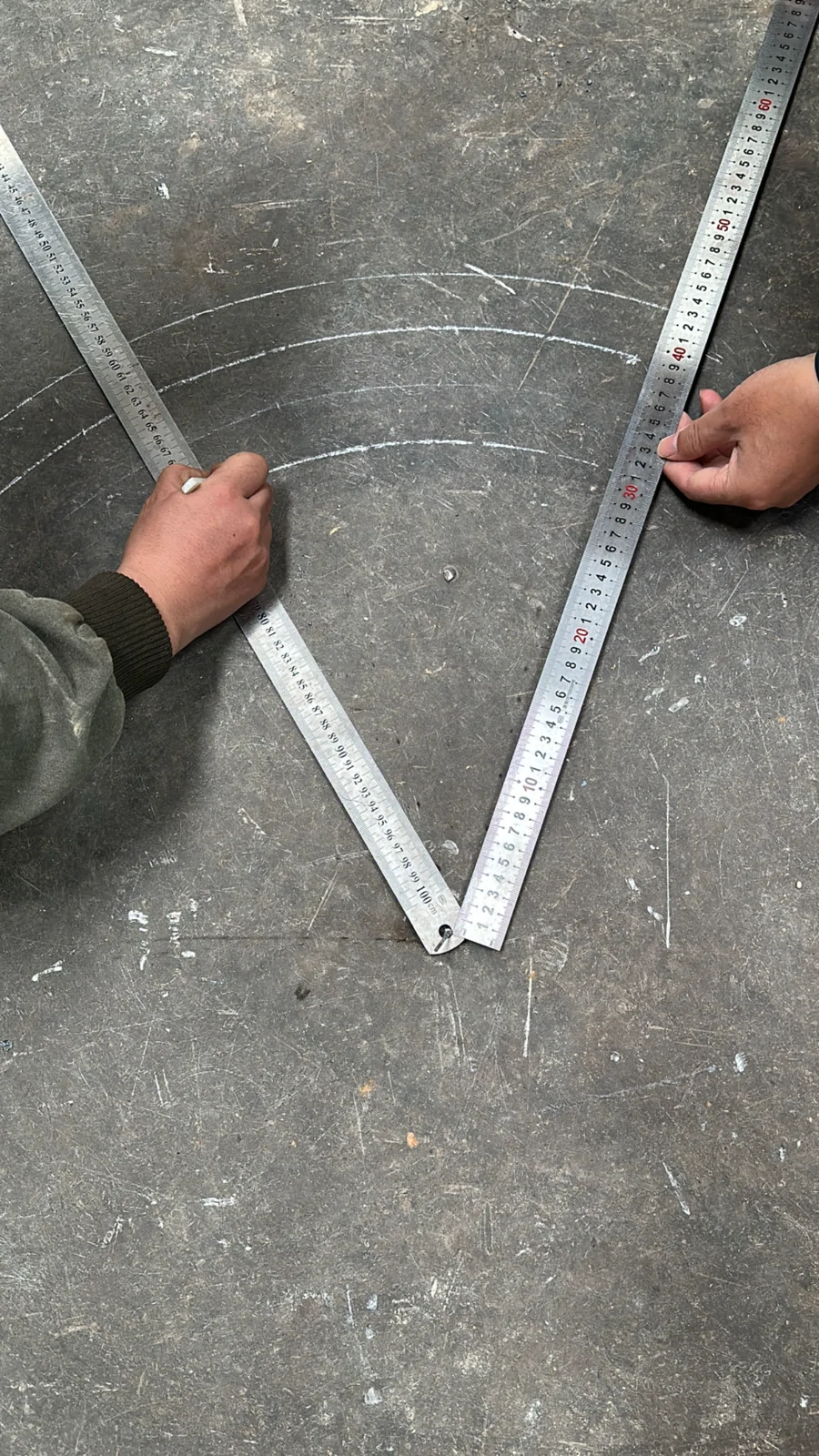
The three circles locate the outer cutting path, the supporting steel ring and the inner cutting path around one centre. They answer different geometry questions; the steel-ring circle cannot substitute for either cutting diameter.
Are the three references clearly separated?
Mark the selected drawing’s references from one centre on the layout surface. Identify which line represents each cutting path and which locates the steel ring before positioning the assembly.
Calculate radial groove width from the two cutting diameters: (outer cutting diameter − inner cutting diameter) ÷ 2. Do not read the gap between the steel-ring line and a cutting line as the full groove width.
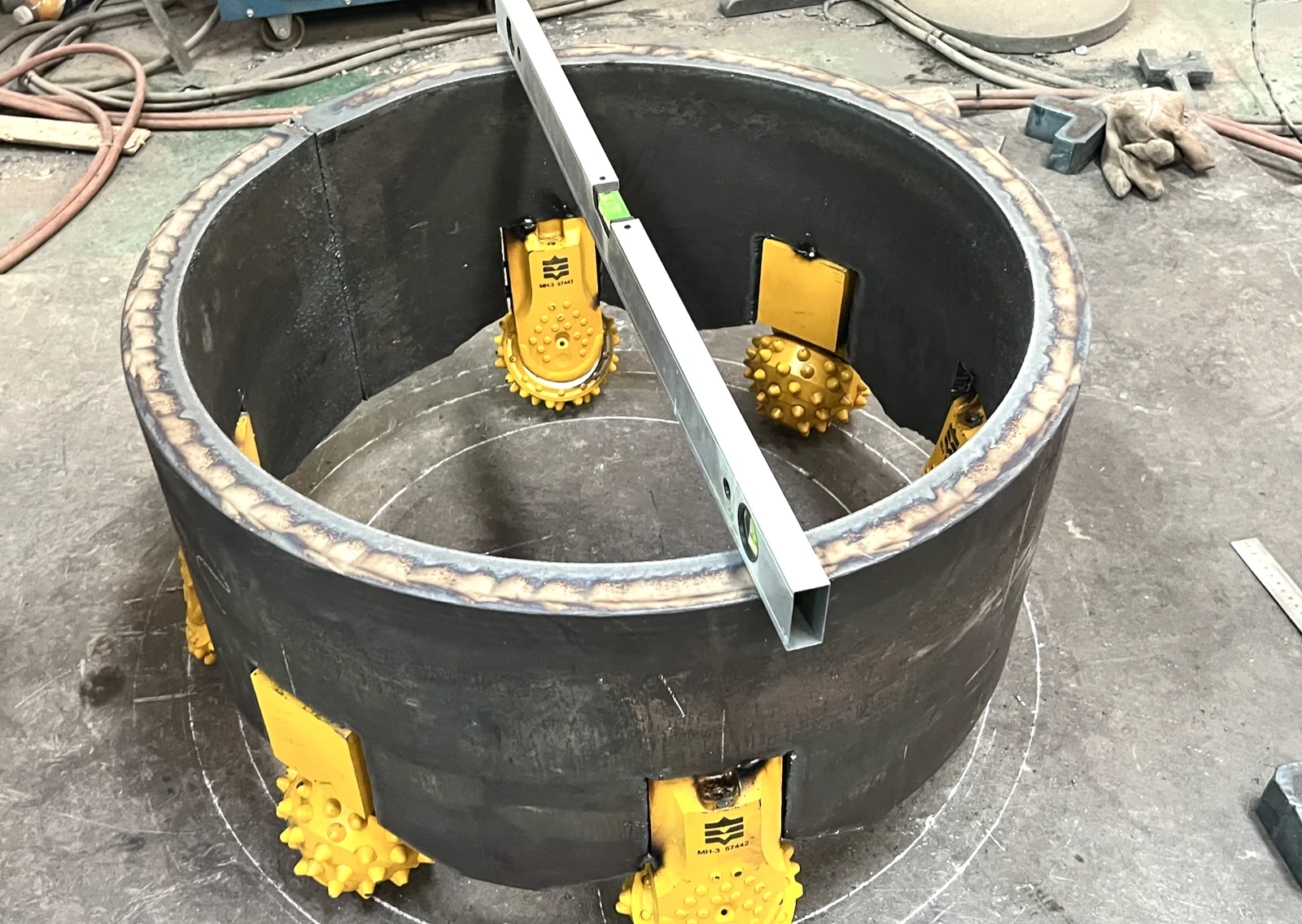
Do the installed cutters follow the intended paths?
The workshop checked the ring against the layout and then checked the inner and outer cutters, including their angle and sideways orientation. A cutter position needs more than a single radial measurement.
After initial positioning, remeasure the complete arrangement and record any adjustment. Use a separate height or projection check alongside the plan-view circles.
Read the actual three-circle example in millimetres
| Marked reference | Diameter | Radius used from the centre |
|---|---|---|
| Outer cutting path | 780 mm | 390 mm |
| Steel-ring reference | 700 mm | 350 mm |
| Inner cutting path | 540 mm | 270 mm |
Cutting groove: (780 − 540) ÷ 2 = 120 mm.
Outer path to ring reference: 390 − 350 = 40 mm.
Ring reference to inner path: 350 − 270 = 80 mm.
The two offsets are unequal in this layout. Dividing the groove into two assumed 60 mm halves would put at least one reference in the wrong place.
- Mark all three circles from the same centre and label each with diameter and radius so a radius is not mistaken for a diameter.
- Locate the steel ring to its own line, using squares to transfer the position to the layout plate.
- Check the outer and inner cutter working points against their own circles, then check projection separately. Correct ring placement alone does not locate the cutting points.