

 WS39 casing tooth
 JM cutter tooth
 B47K22 bullet tooth
Hand rotation checks movement; it does not measure bearing fit. Inspect the journal, mating bores, seal seat and assembled movement against the selected drawing.
01
Measure both sides of the bearing fit
Measure the large and small journal diameters and their corresponding cone bores. Include the axial faces and ball-groove position.
Record measured dimensions and the resulting fit separately from a general “bearing OK” statement.
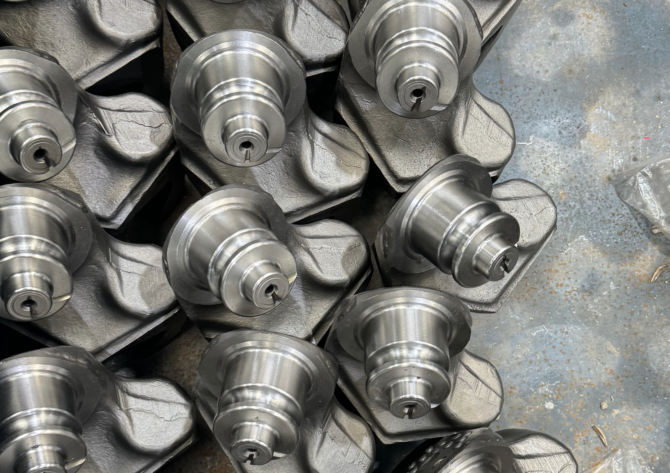
Measure a diameter pattern, not one convenient point
- Clean the journal and bore, remove loose contamination, and identify each mating component and bearing land.
- Measure at more than one axial position and in several directions. A repeated reading in one place can miss taper or an out-of-round section.
- Record journal and bore results separately, then compare the corresponding lands at the same inspection condition.
- After assembly, check axial movement and rotation by the specified method. Keep seal seating and lubricant condition as separate checks.
For a cylindrical pair, a useful dimensional screen compares the smallest bore with the largest journal for minimum clearance, and the largest bore with the smallest journal for maximum clearance. It still does not replace assessment of form, surface condition or the assembled fit.
SKF’s shaft measurement form illustrates multi-position measurement practice. Its rolling-bearing fit limits are not adopted here as roller-bit journal tolerances.
02
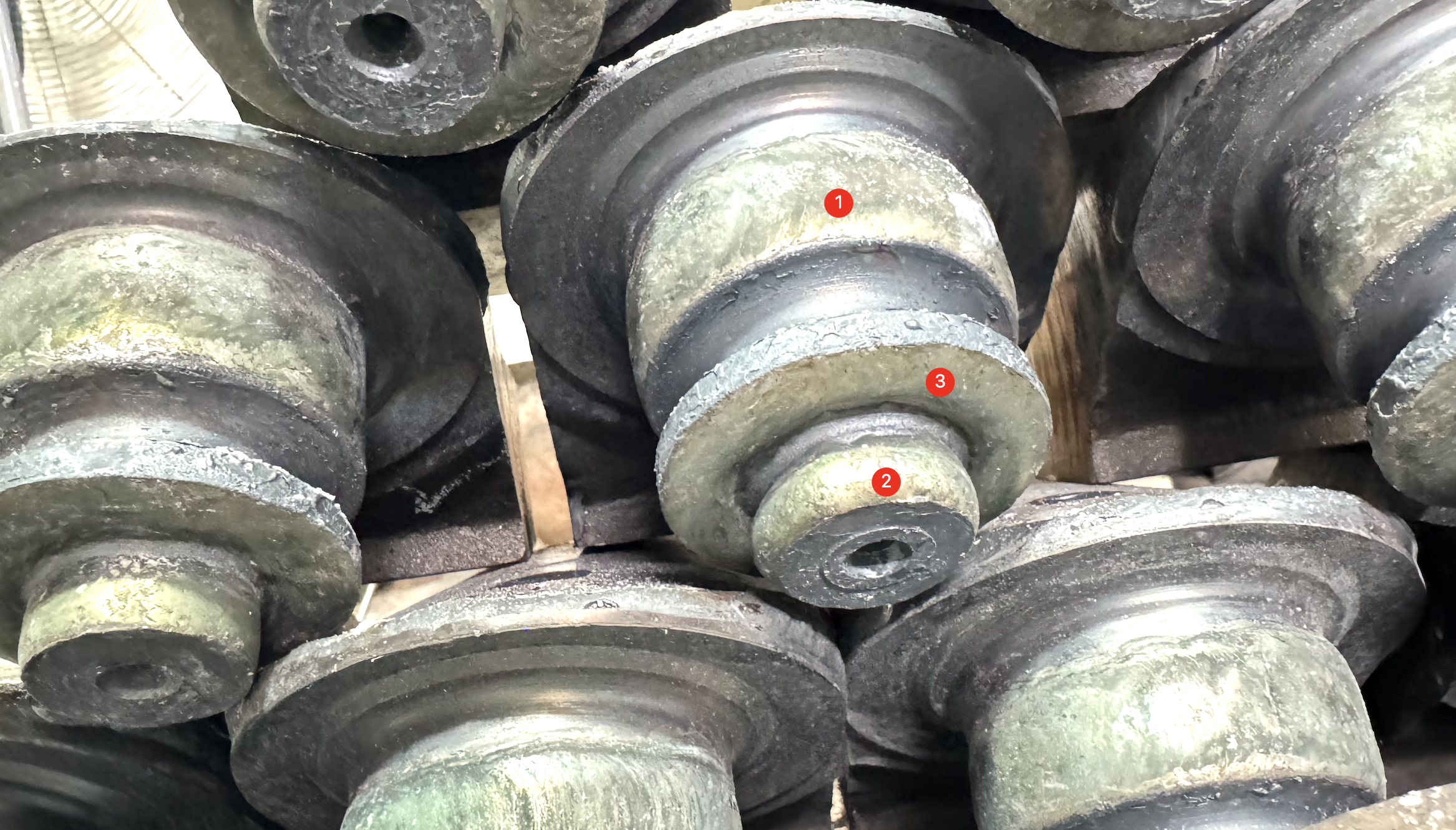
Inspect the final surface, after machining
The MH-3 process example uses deposited hardfacing followed by machining. The deposited layer is an intermediate stage.
Inspect the finished surface for dimensional conformity, surface finish and visible defects. Photographs show the stage; measurements establish conformity.
03
Include the seal and assembled movement
Match the seal-seat dimensions and ring dimensions. After fitting and lubrication, record consistent rotation, any sticking and axial movement alongside the measured clearances.
The design and order define limits and inspection frequency; there is no universal clearance table in this guide.
Use the condition to choose the next check
| Finding | Next check | Why hand rotation is insufficient |
|---|---|---|
| Turns by hand but movement differs by position | Measure the relevant journal and bore lands and inspect for local marks or contamination. | Free rotation does not show whether the clearance varies around the bearing. |
| Noticeable axial movement | Measure axial movement by the specified fixture and loading method; inspect thrust and retaining features. | Feel alone cannot establish the allowed movement or the affected surface. |
| Tight after welding or first use | Review welding heat history, seal condition, fitted geometry and operating record together. | A tight cone has several possible mechanisms; it does not identify one cause. |
| Steel or contamination in the bearing region | Keep the material and inspect mating surfaces, sealing and lubricant condition. | The particles and wear locations help distinguish contamination from surface damage. |