

 WS39 casing tooth
 JM cutter tooth
 B47K22 bullet tooth
ROLLER BITS / MANUFACTURING & QC
Roller-bit
manufacturing.
From the cutting component to the mounting arrangement. Follow the historical MH-3 journal process below, then see the measurements behind the cone-to-journal fit.
TWO COMPONENTS
Two components.
Separate steel grades.
The cone carries the cutting inserts and the mating bearing bores. The leg connects to the drilling tool and carries the journal on which the cone turns.
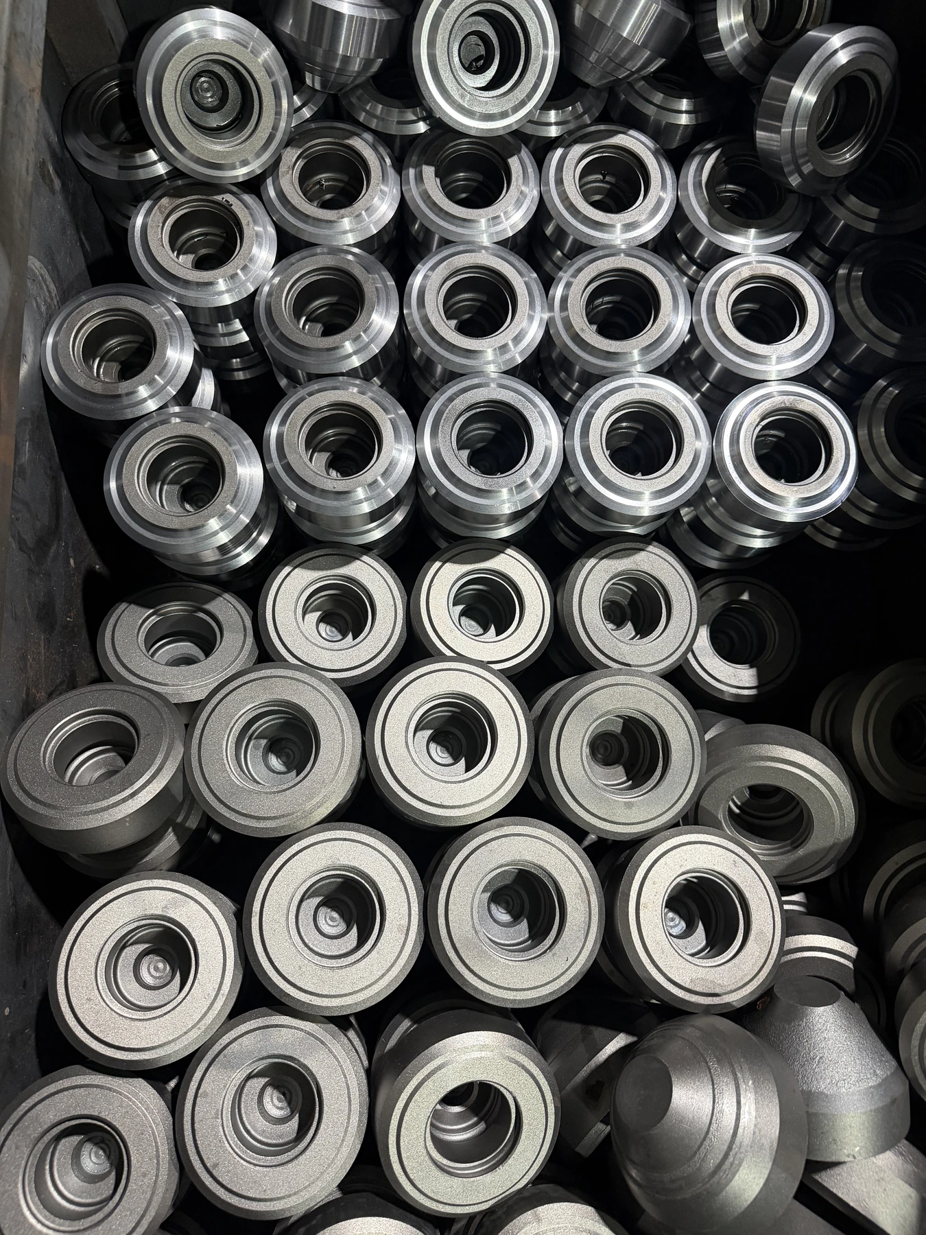
CONE / MH-3 MATERIAL EXAMPLE
15MnNi4MoA
From insert seat to bearing bore
The cone combines insert seats with the large and small bearing bores, ball groove and seal-seat geometry.
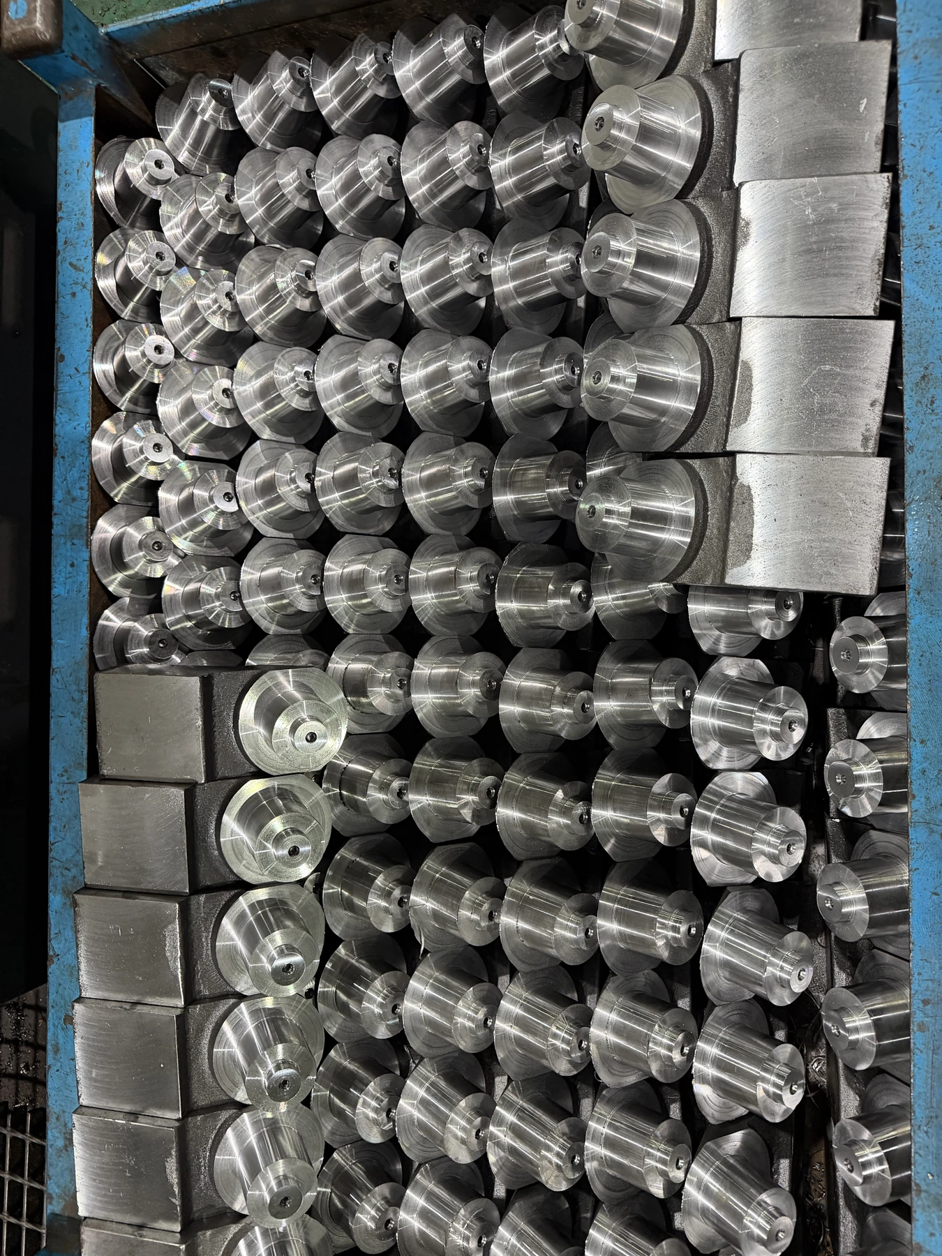
LEG / MH-3 MATERIAL EXAMPLE
15CrNiMoA
From tool connection to journal
The leg carries the journal. Its diameters, bearing-face positions and finished surfaces form the other side of the fit.
Material grades shown are supported by the accompanying 2023 MH-3 records. For a new order, the material specification and inspection requirements are defined with the selected drawing.
JOURNAL MANUFACTURING
From prepared grooves
to finished bearing surfaces.
Follow the recorded MH-3 process: hardfacing, heat treatment and final machining each contribute a different part of the finished journal.
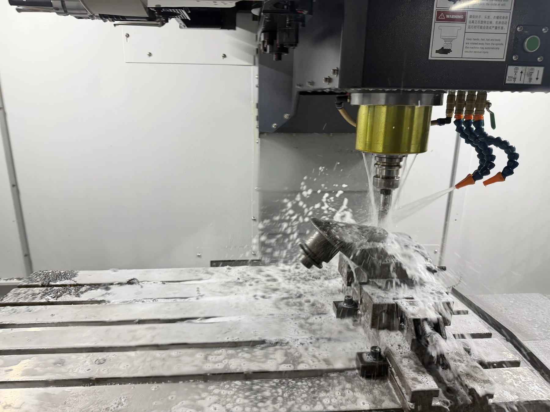
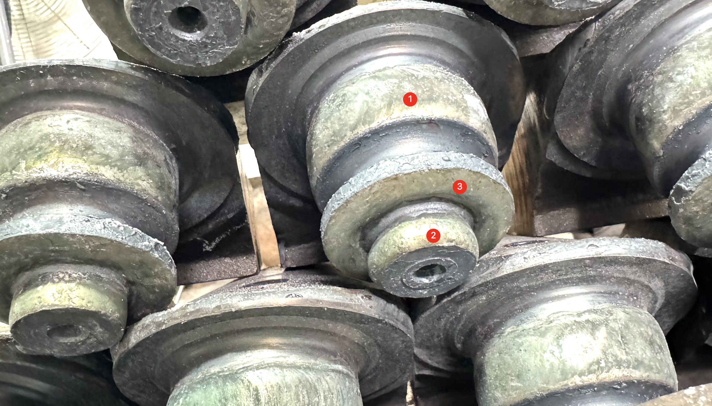
STAGE 01Prepare the grooves
Machine the journal areas that will receive the deposited wear-resistant material.
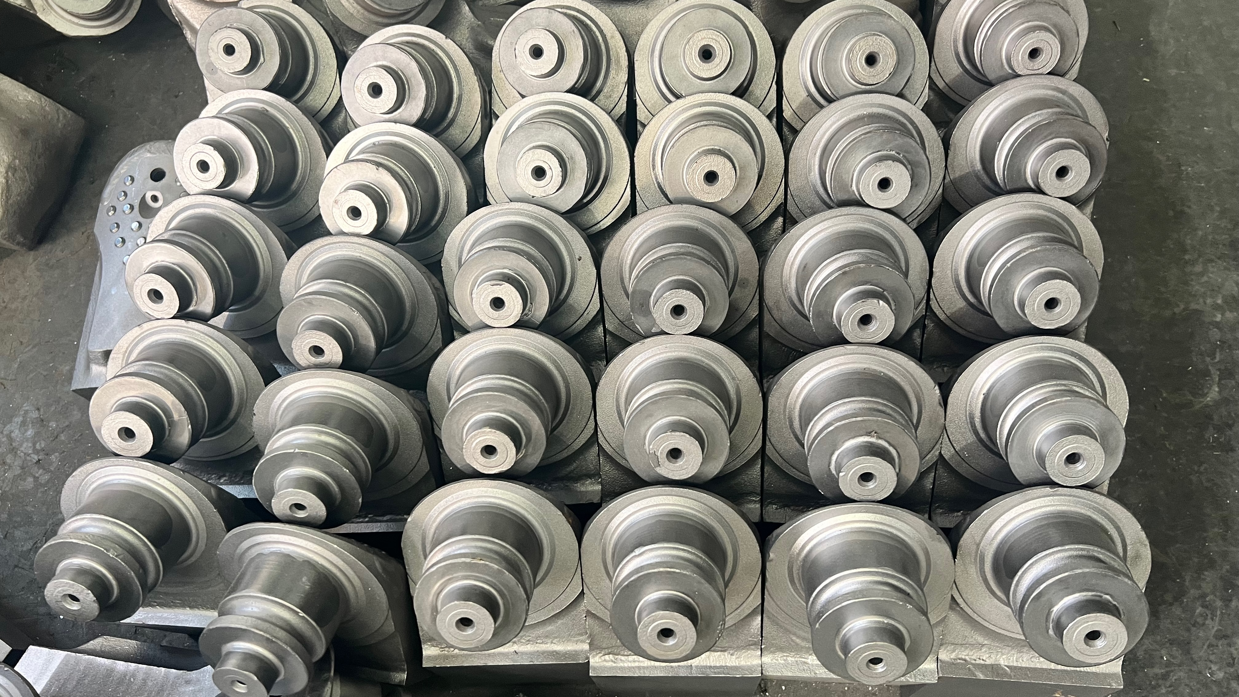
STAGE 02Apply hardfacing
Build up the prepared journal surfaces. The deposited layer is an intermediate stage before final dimensional control.
STAGE 03Pre-machine the part
Bring the leg and journal toward their required form before the heat-treatment stages.
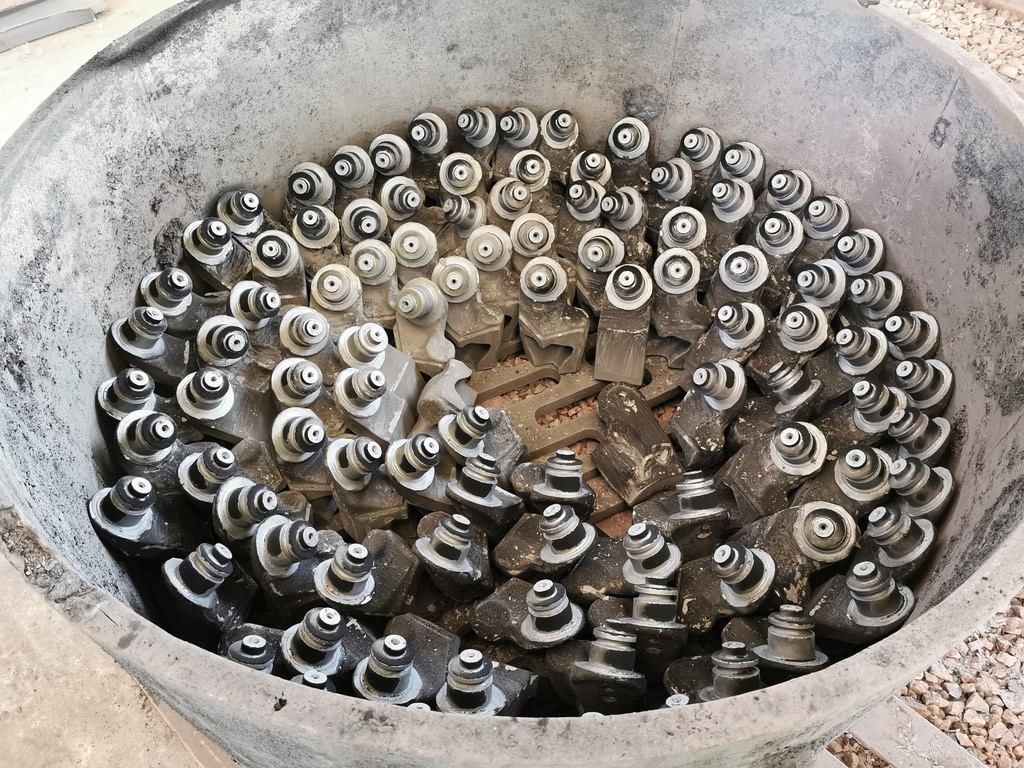
STAGE 04Carburize
The documented process includes carburizing. The photograph shows the legs loaded for this stage.
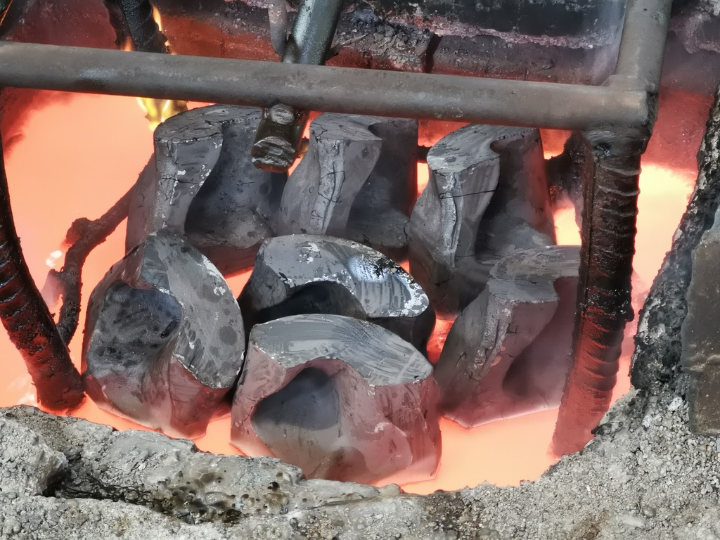
STAGE 05Heat treat
Quenching follows in the process record. This photograph shows heating within that sequence.
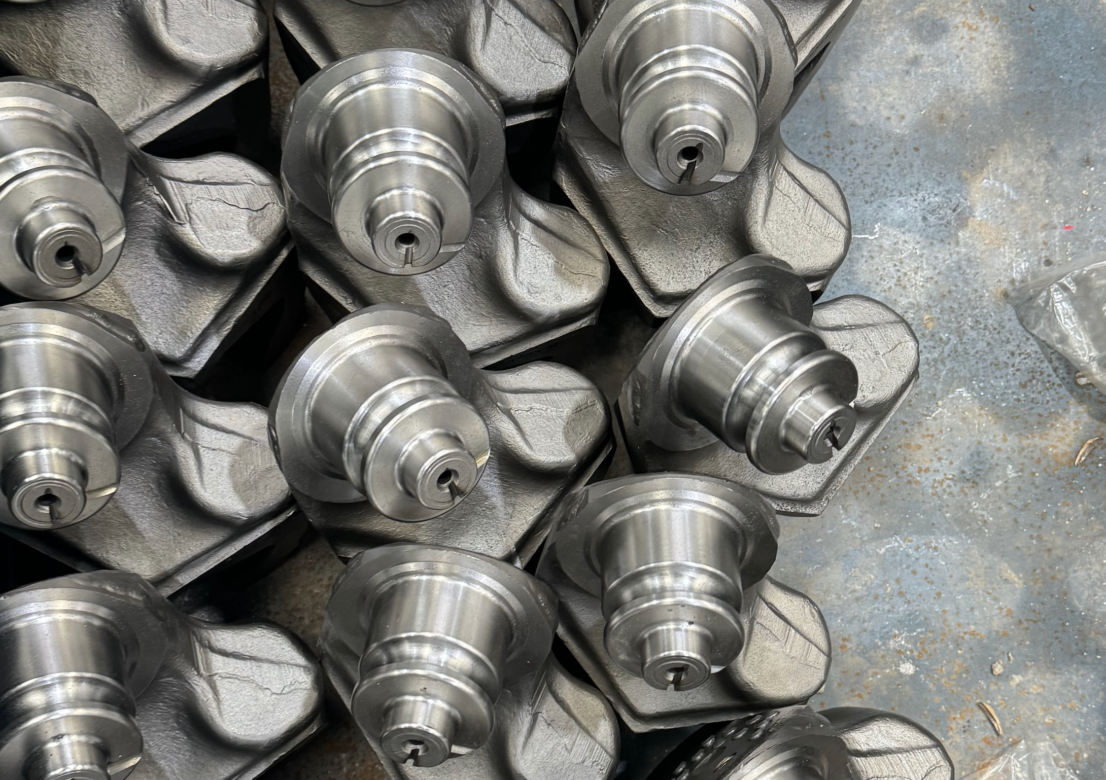
STAGE 06Finish machine
Produce the journal surfaces and dimensional relationships needed for cone assembly.
THE MATING ASSEMBLY
Inspect both sides
of the fit.
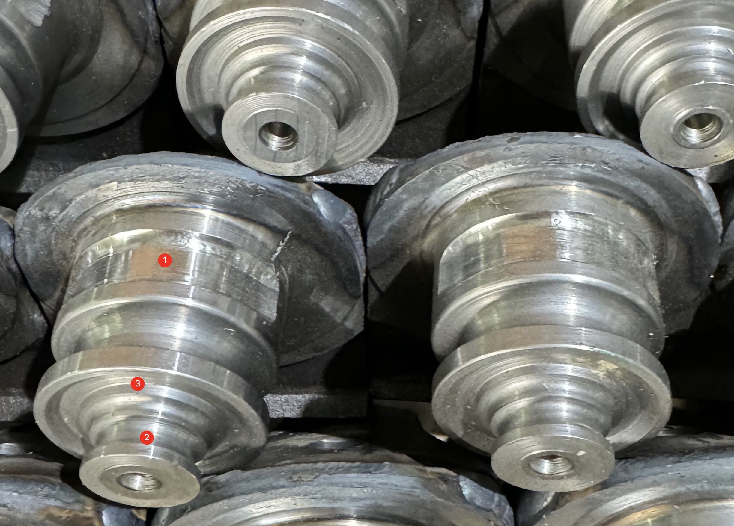
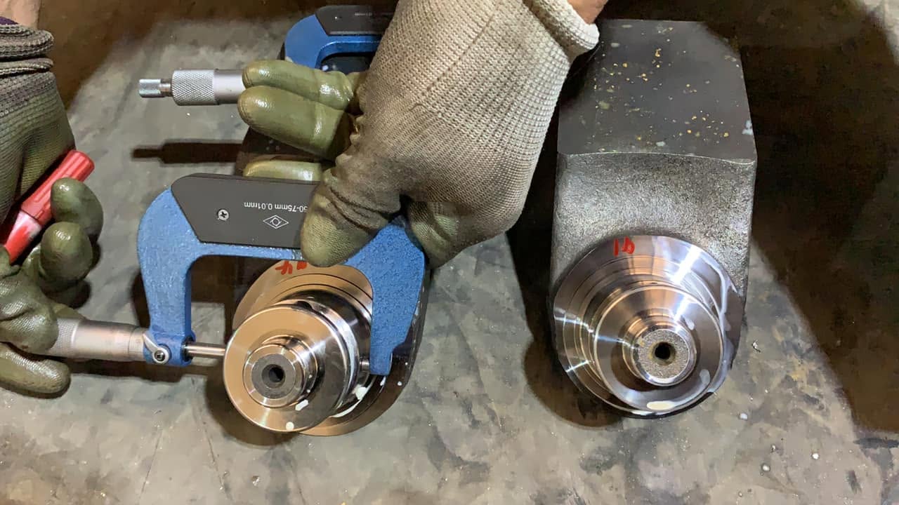
Journal dimensions are measured against the mating cone bores. The seal region, axial movement and rotation then need their own checks at assembly.
Journal and cone
Pair the large and small journal diameters with the corresponding bore measurements. Check the axial faces and ball-groove dimensions against the drawing.
Finished surfaces
Assess dimensional conformity, surface finish and visible defects after machining the hardfacing. The deposited layer is an earlier manufacturing stage.
Seal region
Review the seal-seat and associated ring dimensions together. The seal depends on its surrounding geometry as well as the ring itself.
Clearance and rotation
Record axial movement and journal-to-bore clearance. After lubrication, check for consistent rotation without sticking.
See the journal measurement · December 2020
FROM WORKSHOP TO SITE
Connect the part
to its record.
A useful inspection file links the roller bit to its cone and leg, material and heat-treatment batches, and carbide-insert batch. A later wear observation can then be traced to the actual component.
Follow the same component into field inspection: map the wear pattern and see the 1,200 mm barrel inspection.
This historical MH-3 process example shows the work behind the part. The selected drawing defines the acceptance limits and inspection scope for each new order.
SPECIFY YOUR REQUIREMENT
Specify the roller bit.
Agree the checks.
Send the model, drawing revision, quantity and inspection documents your project needs. We can define the component measurements, material records and assembly checks for the order.