

 WS39 casing tooth
 JM cutter tooth
 B47K22 bullet tooth
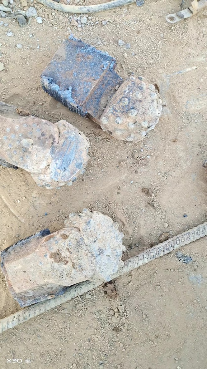
Photograph and number each roller-bit position before removal. Keeping inner and outer positions identifiable helps connect the wear pattern to the cutting layout.
01
Keep outer positions identifiable
Start with a complete cutting-assembly view and number the inner and outer positions. Keep the numbers with the close-ups and with the removed parts.
In this historical comparison, some outer-position wear progressed ahead of inner-position wear.
02
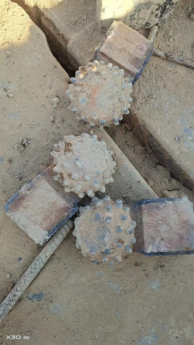
Compare the neighbouring inner positions
Compare inserts and supporting steel at both the nose and wide end of each cone. Read them alongside the neighbouring cutting path and overlap.
The observed pattern belongs to this arrangement; it is not a rule for every core barrel.
Separate project metres, tool metres and individual-part exposure
| Metric | How to count it | Do not substitute |
|---|---|---|
| Project drilling | Pile or hole advance across the project, including all tools used. | Total project metres for the distance drilled by one roller-bit set. |
| Named tool / cutting-set advance | End depth minus start depth for each interval assigned to that assembly. Split the log when the configuration changes. | A headline depth where the first part of the pile was drilled with an auger or bucket. |
| Individual roller-bit exposure | Accumulate only the intervals between fitting and removal for that numbered part. | The tool’s complete history for a replacement bit fitted later. |
For a five-inner/five-outer arrangement, use positions I1–I5 and O1–O5 in the log, alongside the actual part identities. If O1 is replaced, start a new exposure record for the new O1 and retain the removed part’s history. The untouched positions continue their own records.
The 1,200 mm inspection gives a real example: ten positions, an operator-reported 40–50 m and three positions selected for prompt replacement. Those facts are more useful together than an unsupported “50 m per set” claim.
03
Plan the replacement as an assembly
Before mixing new and worn roller bits, compare installed positions and working heights. The review describes keeping selected serviceable inner bits as spares after removing a set.
Keep their position photographs and inspection condition with the spares. No remaining-life percentage was established.
Keep one row for each drilling interval
| Record group | Minimum fields |
|---|---|
| Identity | Date/time; pile ID; rig; tool ID; bit positions or configuration version. |
| Depth and time | Start depth; end depth; cutting time; lifting, cleaning and core-recovery time. |
| Operating context | Ground interval; actual rotary speed; displayed pressure/force name and unit; cleaning changes. |
| Condition and changes | Wear photographs by position; inserts lost/fractured; cone rotation; replacements and reason. |
If cost is compared, state what is included: replacement cutters, holders, welding/repair and downtime are different cost items. Divide only a defined cost total by the corresponding measured advance.