

 WS39 casing tooth
 JM cutter tooth
 B47K22 bullet tooth
800 mm piles · July 2022
800 mm MH-3 barrel: look beyond the carbide tips
DRILLNOVA · Field report · Updated
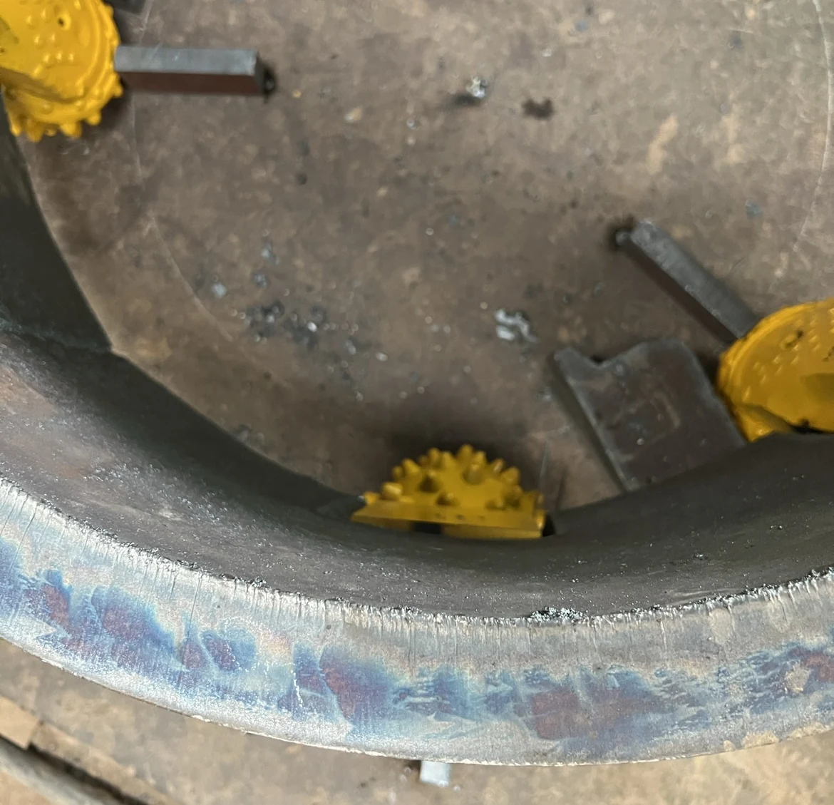
The carbide inserts were still largely intact, but the supporting steel was wearing heavily and one roller cone was difficult to turn. We inspected this six-cutter assembly and reviewed the operators’ drilling cycle to define what needed attention before choosing replacements.
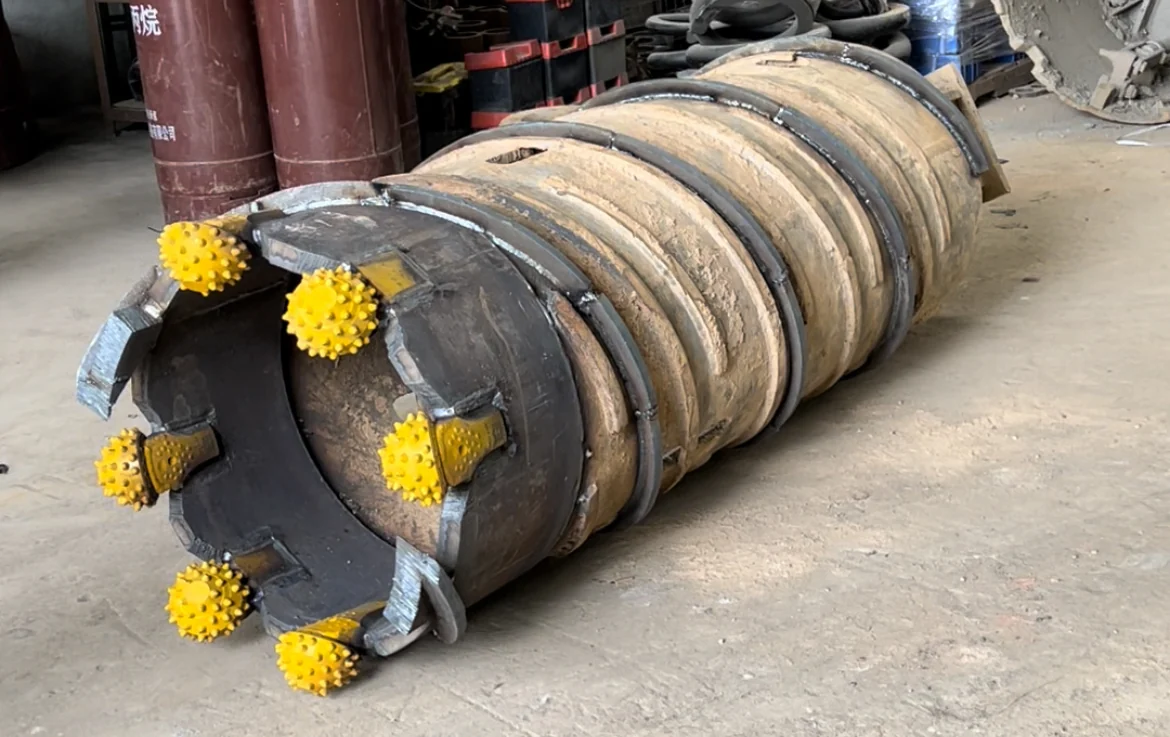
Our review: check the installed cutter positions, improve the cuttings-clearing plan and separate core recovery from rock cutting. The photographs and operating record below show why these became the priorities.
Why the assembly needed a closer look
The site estimated about 15 m of rock drilling across six piles. The barrel had passed through boulders and interlayers into more intact bedrock, yet sticky fines and settled cuttings remained around the working end after lifting. No prepared drilling slurry was recorded. We therefore reviewed how the complete assembly was being cleared and used, alongside the condition of the roller bits.
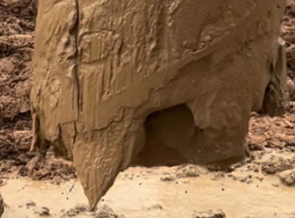
What we confirmed at the inspection
The inspection recorded generally intact carbide and substantial cone-body wear. One cone was seized or difficult to turn, with wear at the leg tip and rear protective inserts. This distinction mattered: looking only at the remaining carbide would miss the wear around it and the loss of free rotation.
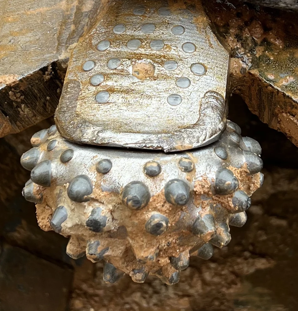
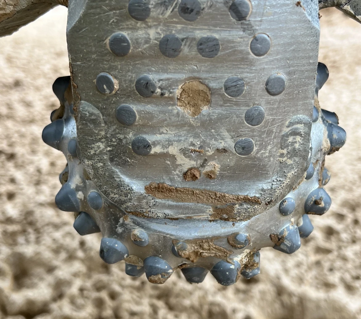
These are views from the same review, not a time sequence of a serial-numbered roller bit.
Our recommendations for the next run
Check the cutter arrangement before replacing the affected unit. The field comparison found that the difficult-to-turn roller bit sat farther outward than the neighbouring outer cutters. We called for a review of projection, clearance and welding position against the complete cutting ring. The associated weld and cooling history also belonged in that check.
Give packed cuttings a route out
For this sticky, fines-rich ground, our proposed follow-up was to review the drilling fluid and plan more deliberate clearing between advances. After lifting, the crew could compare the material retained around the cones, clean the cutters and check for difficult rotation or uneven wear. These checks would connect the next adjustment to an observable change at the tool.
We also recommended reviewing speed and feed pressure with the operator, rather than allowing prolonged loading without clearing. The recorded settings belong to this rig and site; the next operating plan needs to match the actual ground and tool arrangement.
Separate cutting from core recovery
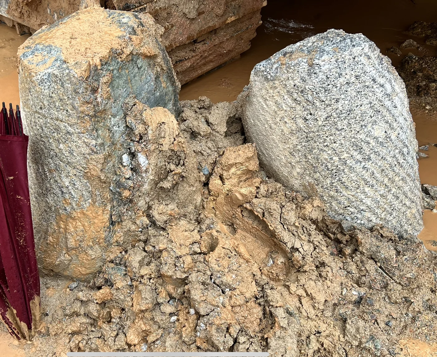
The site had no dedicated core-recovery barrel. The roller-bit barrel was used to cut, fill with core, release it and lift it out. Our recommendation was to provide a separate recovery arrangement for the next site, so the team could plan the core length and recovery stage while reviewing possible impacts on the roller bits. The recovered cores below show why this discussion needed to include the companion tool.
Check the operating pattern against the readings
We compared two Sunward 420 operating windows, pairing the monitor readings with the operator’s feed and clearing technique. The first ran from 35.00 to 35.27 m in 38 minutes. The second recorded short feed pulses, stirring and more frequent lifting. This gave the review an operating record to examine alongside the wear photographs.
| Head speed in log | Time and depth | Advance / elapsed | Calculated window rate |
|---|---|---|---|
| 12 r/min | 10:20, 35.00 m → 10:58, 35.27 m | 0.27 m / 38 min | 0.43 m/h |
| 15 r/min | 12:20, 35.67 m → 13:04, 36.02 m | 0.35 m / 44 min | 0.48 m/h |
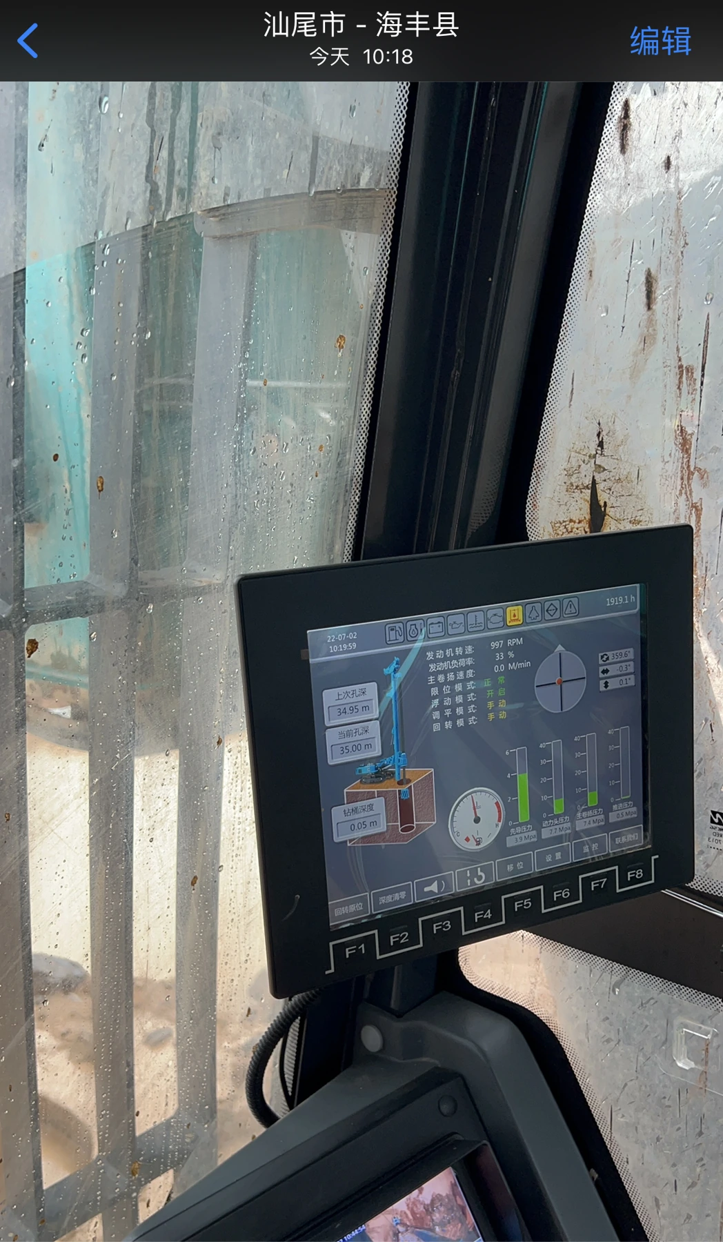
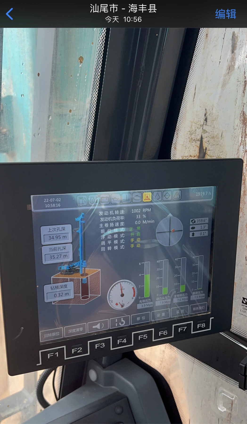
During the first window, the operator advanced the Kelly, worked under its weight and then fed again. The written log gives a feed-pressure display of 0.3–0.5 MPa; this is a hydraulic reading, not a measured load on each roller bit.
The second window—35.67 to 36.02 m, 12:20–13:04, at 15 r/min—used short feed pulses with stirring and lifting between them. Clearing actions changed alongside speed. These elapsed windows include intervening work and establish neither an optimum setting nor a controlled efficiency gain.
Tool configuration and how the readings were interpreted
The separate XCMG 360 observation records 6 r/min, but no quantified feed load.
| Item | Recorded detail |
|---|---|
| Application | 800 mm piling; boulders and interlayers above more intact bedrock |
| Cutting assembly | 6 MH-3 roller bits + 2 scrapers |
| Rigs in the review | XCMG 360 and Sunward 420 |
| Kelly diameter | 580 mm, as recorded in the fluid review |
| Work at inspection | About 6 piles, averaging 2–3 m of rock work each; approximately 15 m reported in total |
| Condition at that point | Carbide generally serviceable; heavier steel wear and one cone difficult to turn |
Calculated window rate = (end depth − start depth) × 60 ÷ elapsed minutes. The two results are 0.43 and 0.48 m/h. They are elapsed observation rates, not isolated cutting rates or full-pile cycle rates.
The approximately 15 m comes from six piles with roughly 2–3 m of rock work each. Individual cutter installation and replacement dates were not recorded.
Inspection findings and proposed follow-up
| Observed problem | Possible contributor to investigate | Proposed response |
|---|---|---|
| Packed fines and rock around cutters | Restricted clearing and repeated contact with trapped material | Review fluid condition and the clearing sequence; compare photos after lifting |
| Steel wear outpacing carbide wear | Repeated abrasion around the cone; installed cutter position | Check the complete cutting ring and compare outer-cutter projection |
| One cone difficult to turn | Packing/heat, welding heat or position, impact, or a bearing/fit issue | Keep the affected unit identified for geometry, weld and bearing inspection |
| Roller barrel also used for core recovery | Contact between loose core pieces and cutters | Plan a separate core-recovery stage and review the companion tool |
These are working explanations and proposed actions. Packing, impact, welding heat or position, and a bearing or fit issue remained possible contributors; no single cause was established. The record does not contain a separate core-recovery trial, controlled post-change result or end-of-life measurement.