

 WS39 casing tooth
 JM cutter tooth
 B47K22 bullet tooth
Shiyan · February 2022
Carbide can remain on a roller bit while the steel holding it is wearing away. The Shiyan photographs showed this loss of support at outward-facing positions. Our review connected the affected roller bits with their installed positions and cuttings clearance, helping define what to check before agreeing replacement parts and repairs to the barrel.
Locate the wear in the complete cutting ring
The 25 February feedback located broken inserts at outward-facing leg-back positions. Original photographs annotate the early ring view as “after half an hour” and the later close-up as “after one day”.
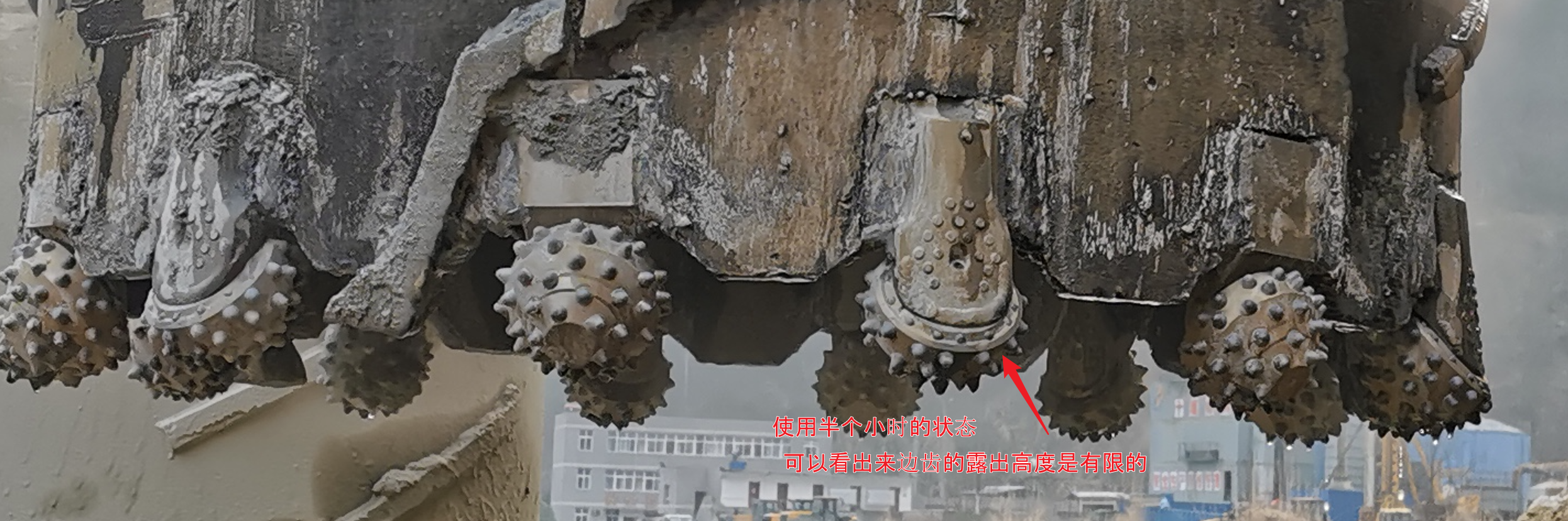
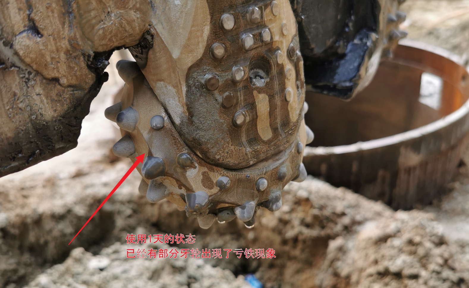
The ring view locates the affected area; the close-up shows insert support. Their time labels do not establish a serial-numbered wear test.
The inspection checkpoint at 22.5 m
The photograph’s 22.5 m of advance annotation identifies severe steel loss around the outer inserts, some described as appearing close to loosening.
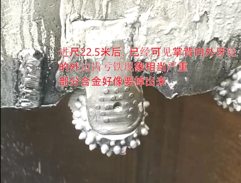
This is a reported inspection point. The starting assembly, cutter count and individual replacement history were not established; 22.5 m is not a verified set life.
Relate visible tip height to steel support
The example section shows a 21.11 mm insert: 9.96 mm exposed and 11.15 mm embedded. It explains how a substantial tip can remain while steel loss leaves less support.
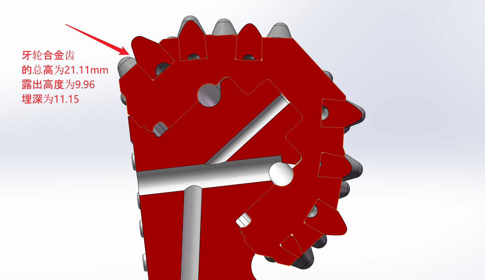
Support loss, detached fragments and recirculating cuttings were considered possible contributors. Operator feedback described lateral Kelly movement on entry: feed was held back until the annular groove formed, then increased.
The author linked this entry behaviour to a check of the cutters’ radial positions from a shared centre. The feed description has no head-speed or pressure values and establishes no cause; it identifies an installation question.
Trace the clearing route around the affected positions
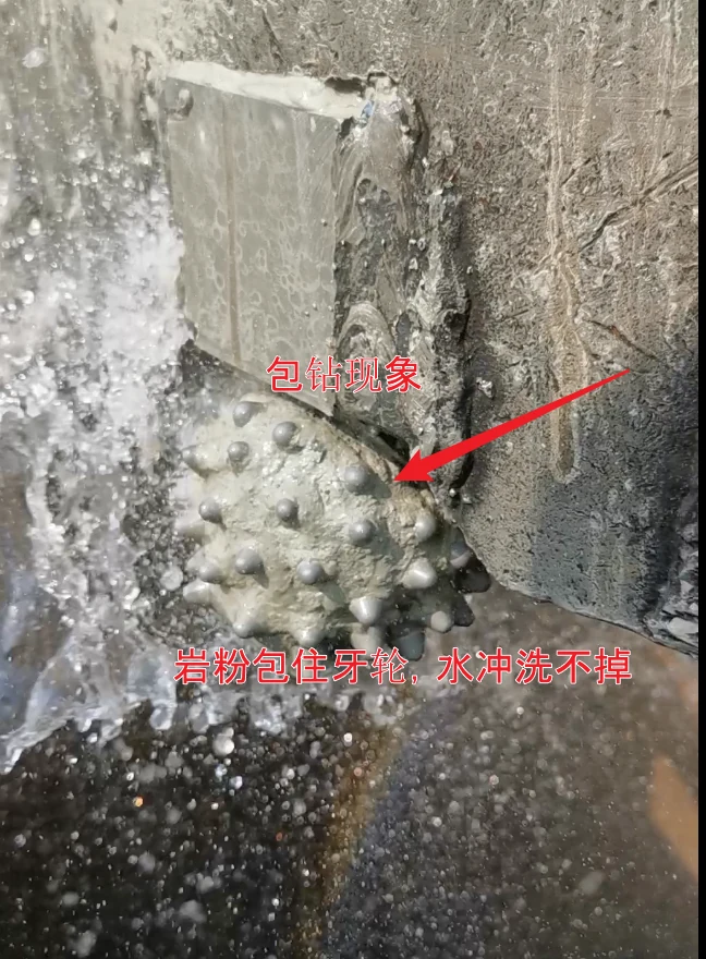
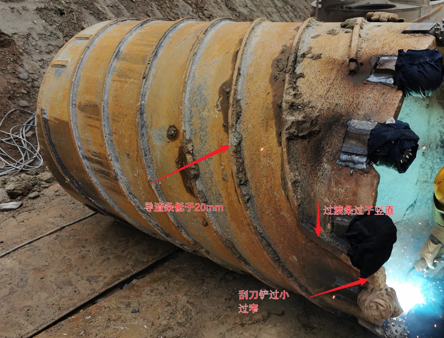
Remaining guide height was estimated at 10–15 mm, with a narrow scraper and abrupt transfer route. The packed material prompted a proposed review of that route, guide height and spoil removal with the drilling bucket.
The next checks were cone rotation, steel support and projection against neighbouring cutters. Missing or fractured material also called for hole-cleaning and recovery planning within the site method.
Illustrated dimensions: what 3 mm of steel loss would mean
| Dimension | Recorded example |
|---|---|
| Total insert height | 21.11 mm |
| Height exposed above the steel | 9.96 mm |
| Depth embedded in the steel | 11.15 mm |
The dimensions add up: 9.96 + 11.15 = 21.11 mm.
Remaining embedded depth: 11.15 − 3 = 8.15 mm
This one-dimensional illustration assumes the steel surface recedes 3 mm along the insert axis while the insert stays in place and its tip does not wear. It is not a field measurement or a discard limit. Irregular side wear cannot be reduced to this subtraction.
Inspection findings and proposed actions
| Observed or reported | Mechanism to examine | Action proposed in the review |
|---|---|---|
| Remaining guide-strip height estimated at 10–15 mm after wear; narrow scraper and abrupt transfer route | Cuttings remaining near the working face and recirculating around the cone body. | Review the scraper opening, transfer route and guide height as one cuttings-removal system. |
| Packed material around the roller bits | Restricted cleaning and cooling around the steel, seals and bearing region. | Increase inspection/cleaning opportunities and coordinate spoil removal with the bucket. |
| More severe damage at affected outward-facing positions | Unequal cutter projection, local contact and loss of steel support. | Check the installed positions from a shared centre and compare neighbouring inner and outer cutters. |
| Fractured or missing inserts | Loose fragments may contact the remaining cutters. | Inspect for missing material and arrange hole cleaning/foreign-object recovery within the site method before continued drilling. |
These responses were proposed, not verified improvements. Their effectiveness would need a subsequent dated inspection, numbered photographs and drilling log from the same tool. This record contains no set-life result or post-change performance measurement.