

 WS39 casing tooth
 JM cutter tooth
 B47K22 bullet tooth
When a roller-bit barrel slows down, separate cutting time from clearing and core recovery. Find where the cycle loses time before replacing cutters; low hourly output alone does not identify the restriction.
All checks in this guide
01
Find where progress is being lost
If the reported rate is “0.2 m/h”, first confirm what the hour includes. Record metres advanced and active cutting time separately from time spent lifting, lowering, clearing, recovering the core and changing tools. Keep the depth interval and start/stop times with each value.
A sudden change and a steady decline are useful starting descriptions, not diagnoses. Select the closest pattern, then inspect the tool and ground conditions before changing the settings or cutters.
| What changed? | Start with | Bring to the review |
|---|---|---|
| It slowed down suddenly | Mark the onset depth and the last normal interval. Check what changed in the ground, tool, cuttings or clearing sequence at that point. | Before-cleaning photos, cone movement, the depth record and the last known settings. Discuss a sudden slowdown |
| Progress declined over several intervals | Compare wear and packed material by cutter position alongside changes in ground and operating conditions. Track the same barrel and its cutter replacements, especially when tools move between rigs. | Dated tool photos, metres or hours for the affected cutters, and cutting/clearing times from comparable intervals. Discuss a gradual decline |
| It cuts, but the full cycle is slow | Separate cutting from clearing and core recovery. Check the cutting envelope and the companion recovery tool before treating the delay as a cutter problem. | A timed cycle, core dimensions and condition, recovery-tool details and where the sequence stalls. Review the cutting and recovery sequence |
If the slowdown includes a stuck or loose cone, use the cone-condition checks before returning the tool to service. If the barrel jumps, follow the vibration inspection sequence.
Shiyan · March 2022
Log the clearing step alongside the depth
The second Shiyan visit recorded mud accumulation, clearing and renewed cutting in the same daily log. Keeping the action beside the depth makes the sequence useful; reporting only a daily metres-per-hour figure would hide it.
8 March: one recorded sequence
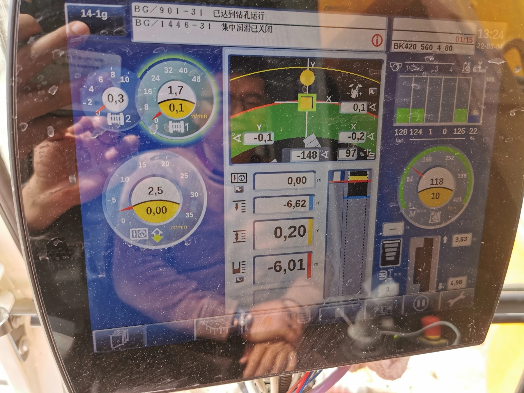
- 10:00 · 7.90 m. The note described substantial mud and bore collapse.
- 11:10 · 8.26 m. Drilling restarted after clearing with the drilling bucket.
- 11:42 · 8.43 m. The next depth was logged. The interval does not separately identify every cutting and interruption period.
The follow-up review called for checking the scrapers and guides alongside cutter position, cutting height and possible loose material in the bore. It did not isolate one cause for every slow interval.
Historical log: readings and measurement limits
- The 8 March note says advance was approximately “50” after clearing and “30” without clearing. It does not define a common time basis or explicit units for these two figures, so they cannot support an improvement percentage.
- The same note gives P1/P2 at about 180 and rotation at about 10–11 rpm. The pressure channels and units were not identified. These are historical entries, not operating settings for another rig.
- On 4 March, the log gives 6.64 m at 16:56 and 6.61 m at 17:40, followed by 6.82 m at 17:50. The apparent depth reversal is retained rather than silently corrected. The separate display photograph shows 13:24 and −6.62 m; it cannot be aligned to those later entries.
For a comparable follow-up, retain the rig and tool identity, depth/time readings, actual cutting periods, lifting and clearing times, and photographs before cleaning. This March operating log is separate from the earlier Shiyan steel-loss photographs; it does not establish a shared hole, unchanged cutter set or service-life endpoint.
02
Inspect before washing away the evidence
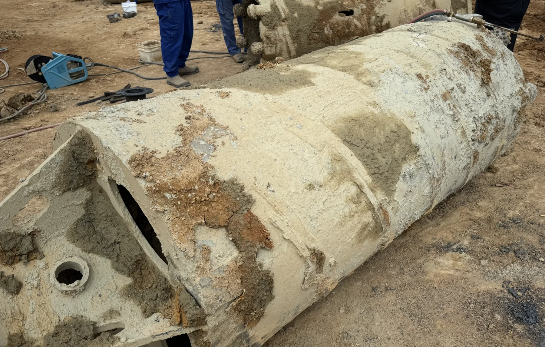
Support the tool securely against movement or rotation before approaching. Before cleaning, photograph material around the cones, openings, scraper and guides from safe positions. Then clean and check cone rotation, wear, inserts and looseness. Keep both views: packed material and mechanical condition answer different questions.
The June 2025 Jieyang review found worn cuttings guides, variable slurry conditions and difficult core recovery alongside changing rock profiles. These were interacting inspection findings, not proof that one defect caused every slow interval. The same review also noted barrels moving between rigs and assemblies containing new and worn cutters.
| What you see | Check next | Do not assume |
|---|---|---|
| Material packed around the bits | Openings, guides, scraper position, fluid condition and clearing sequence. | That extra crowd will restore a blocked path. |
| One-sided wear or a cone that will not turn | Clean rotation check, looseness, mounting position and neighbouring wear. | That appearance alone proves a material fault. |
| Jumping after entering a new layer | Rock engagement, cutter geometry, rig/Kelly condition and settings. | That every impact comes from the same cause. |
| Repeated delays taking the core | Core dimensions, integrity and the matched recovery tool. | That a different roller bit will solve the recovery step. |
03
Follow the route out of the cutting zone
Thrust and rotation bring inserts into contact with fresh rock, where fractures form and chips must leave the contact zone. If debris stays there, repeated crushing can consume effort without equivalent advance. Larisch describes this mechanism for air-roller core barrels; the operating settings remain specific to that system.
Inspect the cones, ring openings, scraper and guides as one connected cuttings route. Pay particular attention to the junction between the scraper and the external guide: an open space beside the cone can still lead into a tight pocket farther along the route.
With the tool supported and isolated, photograph the junction before cleaning. Check for compacted chips, narrowing passages and worn or displaced guide edges. Compare packed material with the intended route to the outer guide before assuming that more flushing is needed.
Restore or revise the passage against the assembly layout, then compare cutting and clearing time in a suitable trial interval. The correct offset depends on the cutters, scraper and guide geometry; a dimension copied from another barrel is not a clearance specification.
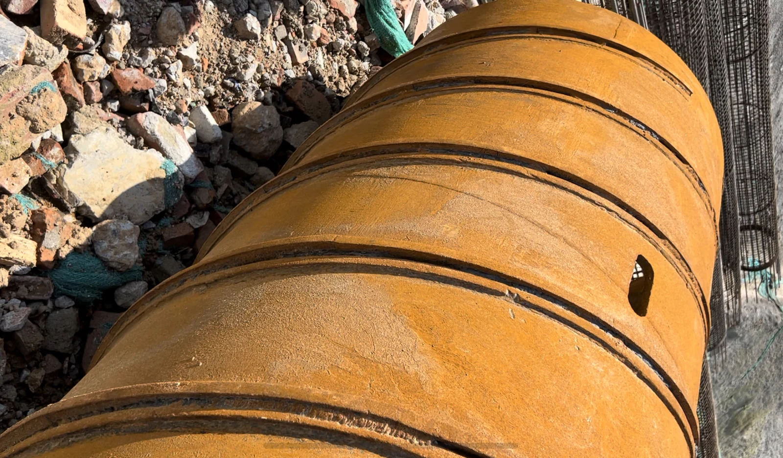
Review fluid level, cuttings suspension and conditions at depth with the site team. Use the project’s bore-support and fluid-control requirements; surface appearance alone does not show conditions around the barrel.
Choose an action that addresses the observed restriction: clear the bore, restore the guide profile, correct a passage or revise the working sequence. Compare the next suitable interval using separate cutting and clearing times. Finer debris alone does not prove a blockage or justify more RPM.
Technical background: M. Larisch, Comparison of different hard rock drilling methods for bored piles, 16th Australian Geomechanics Symposium, 2012, section 3.2.
04
Match the cutting and recovery tools
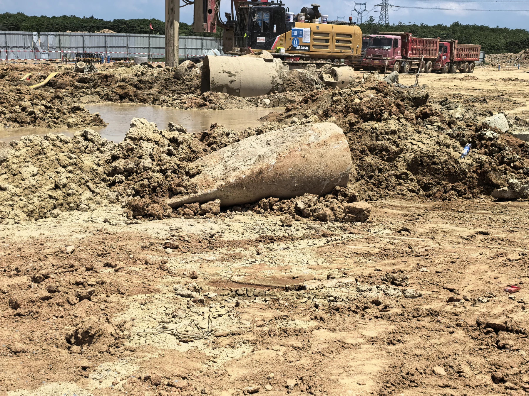
Compare the actual cutting envelopes of tools used in sequence. At the start of the Jieyang trial, the new barrel first had to enlarge a smaller hole made by a bullet-tooth barrel. The team then moved it to a newly started pile. That reaming interval could not be interpreted as ordinary bottom-hole penetration.
Core recovery deserves the same attention. A longer barrel or a different internal gripping arrangement is not automatically an improvement: rock integrity, core size, available torque and lifting conditions change the requirement. Keep the cutting task and the planned recovery task explicit when selecting a configuration.
05
Verify the change before calling it an improvement
Make the smallest change that addresses the finding. Keep before-and-after measurements and photos; compare cutting and interruption times on the same basis. If guides, cutters and settings change together, report the combined result rather than attributing it to one component.
Stop and investigate if a cone is seized, loose metal is suspected, mounting integrity is doubtful, or unstable behaviour persists. Return to drilling only after the tool and bore condition have been assessed. A useful follow-up shows both acceptable cutting behaviour and acceptable inspection condition; it does not turn a single trial into a guaranteed service life.