

 WS39 casing tooth
 JM cutter tooth
 B47K22 bullet tooth
DRILLNOVA / ROTARY DRILLING TOOLS
Double-wall casing
Inner and outer tubes, end joints and the drive connection form a matched casing section. Specify the clear passage and mating interfaces before choosing individual components.
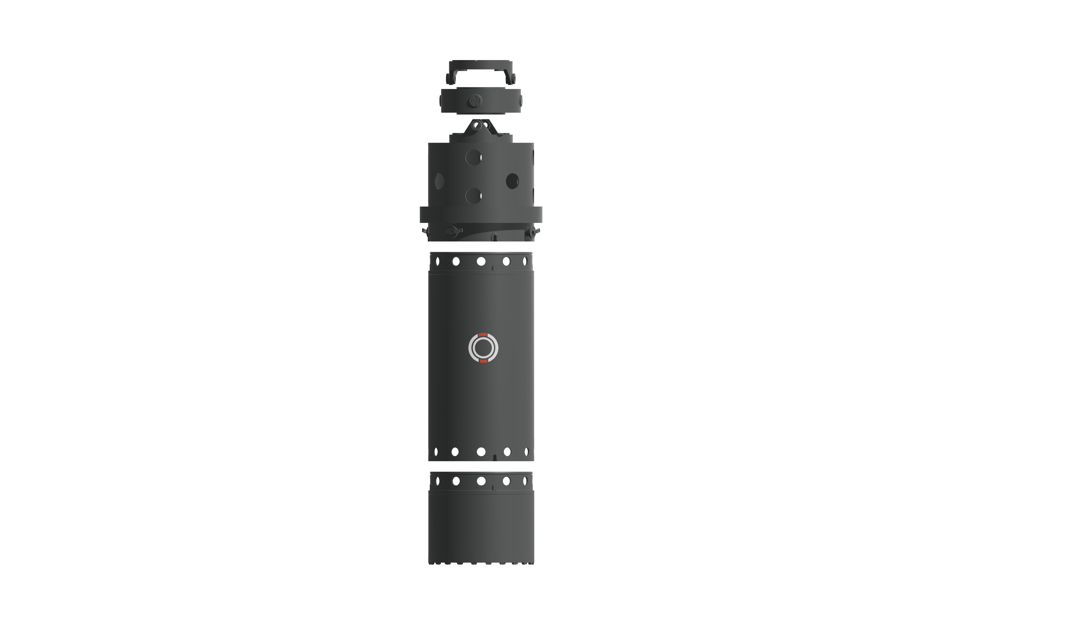
Review the connection before the complete length.
Specify the section and its two connections
A double-wall casing section combines inner and outer tube walls with end-connection details. The section belongs to a casing string that also includes a casing drive adapter, connecting components and a casing shoe. The tube dimensions and the mating geometry answer different questions and both need a defined reference.
Outside diameter, inside diameter, section length and wall construction describe the tube. End geometry and hole patterns identify how it joins the neighbouring components. Two sections with the same nominal diameter should not be treated as matched until those interfaces agree.
| Requirement | What stays / changes | Matching reference |
|---|---|---|
| Add or replace a section | The existing string and its connection system remain the starting point. | Both section ends, tube dimensions and the existing system drawing. |
| Change section geometry | Length or wall construction is revised while mating components may be retained. | Revised section drawing plus explicit confirmation of the retained interfaces. |
| Specify a complete system | Casing sections, joints, drive adapter and casing shoe are reviewed together. | A component list showing every mating pair and the scope of supply. |
Keep tube and joint inspection connected
Measure the tube and both end connections against the selected drawing, including profiles, mating surfaces and hole positions. Mark the measurement references at each end; overall photographs cannot replace these checks.
Fabrication and weld inspection should follow the requirements specified for that section. The inspection file should distinguish drawing targets from actual results and identify any correction before acceptance. Where a mating-component check is required, retain the identity of the component used for that check rather than recording only “fits”.
When adding sections to an existing string, include the condition of the retained mating parts. Worn holes, damaged seating surfaces or deformation may change the work from supplying a tube to reviewing a connection. Keep that condition record with the new-section requirement.
Separate tubes from shoes, drives and accessories
List the quantity and reference of each section, then identify whether shoes, joints, drives or adaptors are included. This makes quotations comparable and gives the receiving team a practical list to check against the delivered components.
See the complete casing-system components or review the casing-shoe interface.
Section dimensions, material requirements, connection details and inspection acceptance are agreed for the selected system. Keep that specification with the component list and quantity schedule.
PRODUCT & PROJECT ENQUIRY
Review casing sections and their connections
Send the required section dimensions, connection reference and quantities, with photographs of any existing mating parts. Identify whether shoes, joints, drives or adaptors are included in the requested supply.