

 WS39 casing tooth
 JM cutter tooth
 B47K22 bullet tooth
DRILLNOVA / ROTARY DRILLING TOOLS
Drilling augers
The pilot, cutting head and flights work together. Compare straight and conical rock augers through their lower geometry, cutting envelope and flight arrangement.
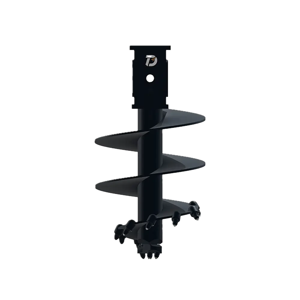
Compare the complete flight and cutting-head arrangement
The straight and conical rock-auger references show different lower-tool geometries. The comparison should follow the tool from its drive connection, along the flights, to the cutting head. A similar overall length or diameter does not identify the same working arrangement.
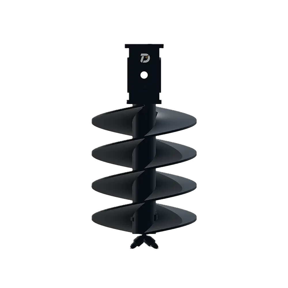
| Feature | Straight reference | Conical reference |
|---|---|---|
| Lower geometry | Straight flight configuration with the cutting head at the lower end. | Conical lower cutting arrangement, with teeth positioned around the working geometry. |
| Cutting layout | Check the head, teeth and holders as the specified straight-tool assembly. | Check the position and projection of each cutting component against its own layout. |
| Common comparison fields | Working diameter, length, flight profile, cutting-part references and drive interface should use the same named measurement points. | |
Separate the flight profile from the wear-part interface
The flight is part of the tool’s geometry and material-handling path. The tooth and holder define a local cutting interface. Changing the cutting part should therefore trigger a check of its working projection and the nearby head and flight, rather than being treated as a model-name substitution.
For a new assembly, the drawing review should identify the centre reference, flight profile and cutting-head positions together. During fabrication, retain measurements of the specified geometry and the connection alongside the inspection of the head and flight attachment areas. The acceptance values and welding requirements belong to that assembly’s drawing and procedure.
Before repair, photograph the worn head and flight edges. Separate tooth wear from damage to the holder or supporting steelwork so the quotation covers the parts that need attention.
Choose a defined configuration
A useful comparison identifies which existing tool is being replaced and what should change: the lower geometry, cutting system, flight arrangement or complete assembly. Keep the intended ground and operating task with that comparison, then confirm the selected configuration and connection.
Use the selected configuration drawing for dimensions, connection details and acceptance values. The two illustrations do not establish a universal ground-strength range or rig compatibility.
PRODUCT & PROJECT ENQUIRY
Review a straight or conical rock auger requirement
Identify the straight or conical rock-auger configuration, required working size and drive connection. Include ground conditions and existing tool photographs, and state whether you need a complete auger or a cutting-head repair.