

 WS39 casing tooth
 JM cutter tooth
 B47K22 bullet tooth
Choose the mounting system from your existing tool and replacement plan: a weld-on leg, a matched holder or a bolted assembly. Confirm the interface before comparing prices; similar cone shapes do not establish fit.
Will the welded leg fit the cutting ring?
Check the leg profile against the opening, then confirm radial position, projection and orientation from the selected layout drawing. A worn opening is a condition to inspect, not a reliable template for the replacement.
Agree the installation sequence and welding heat controls before work starts. The bearing, seal and lubricant are part of the assembly that the installation procedure must protect.
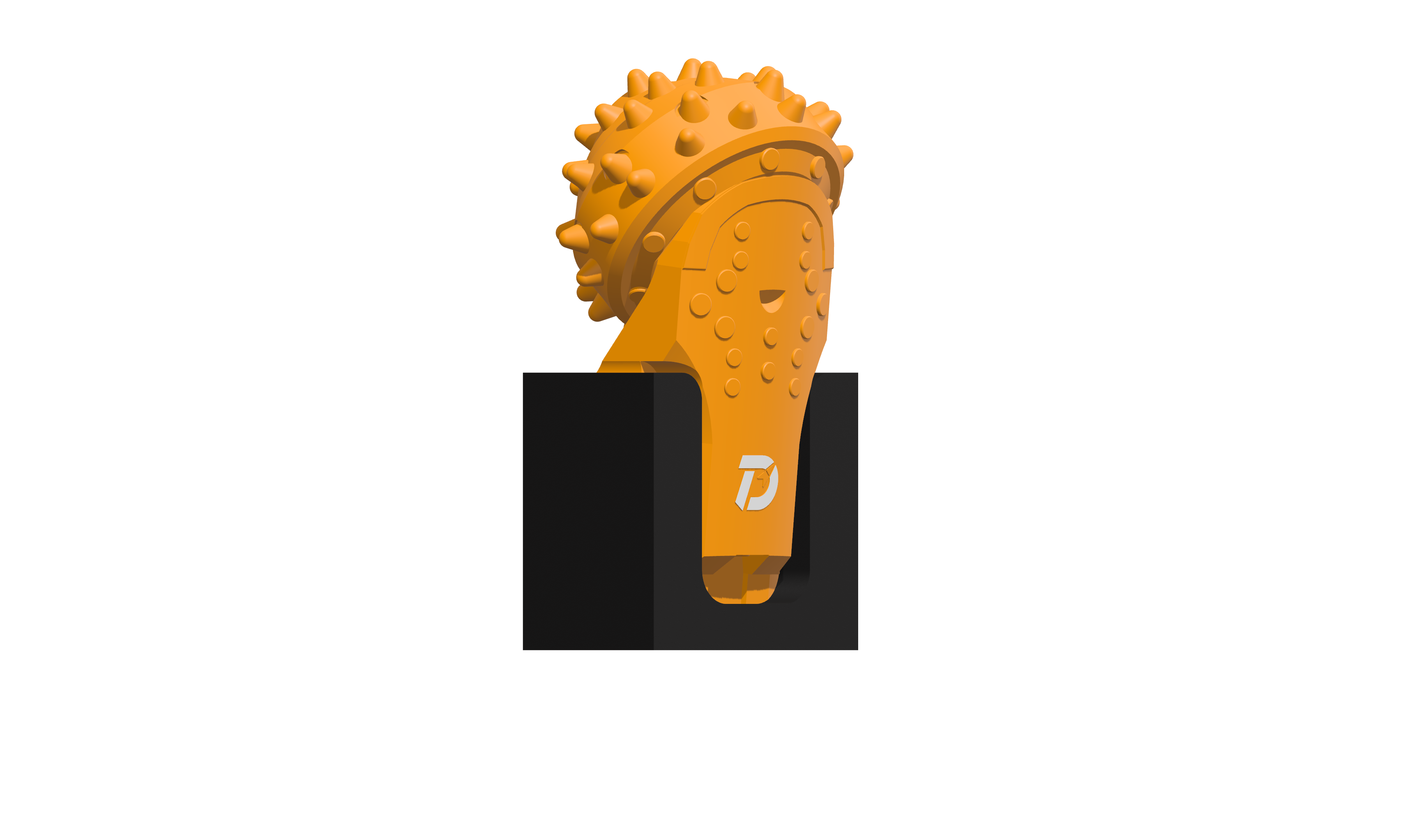
Is the replaceable assembly matched to its holder?
For a holder-mounted roller bit, identify both the bit and holder and confirm the seating interface and retention method. For a bolted version, check the existing beam, bolt arrangement and surrounding clearance.
Include the space needed to remove the worn part and fit the replacement. Do not assume interchangeability between holder, bolted and weld-on families.
Plan the installation before choosing weld-on
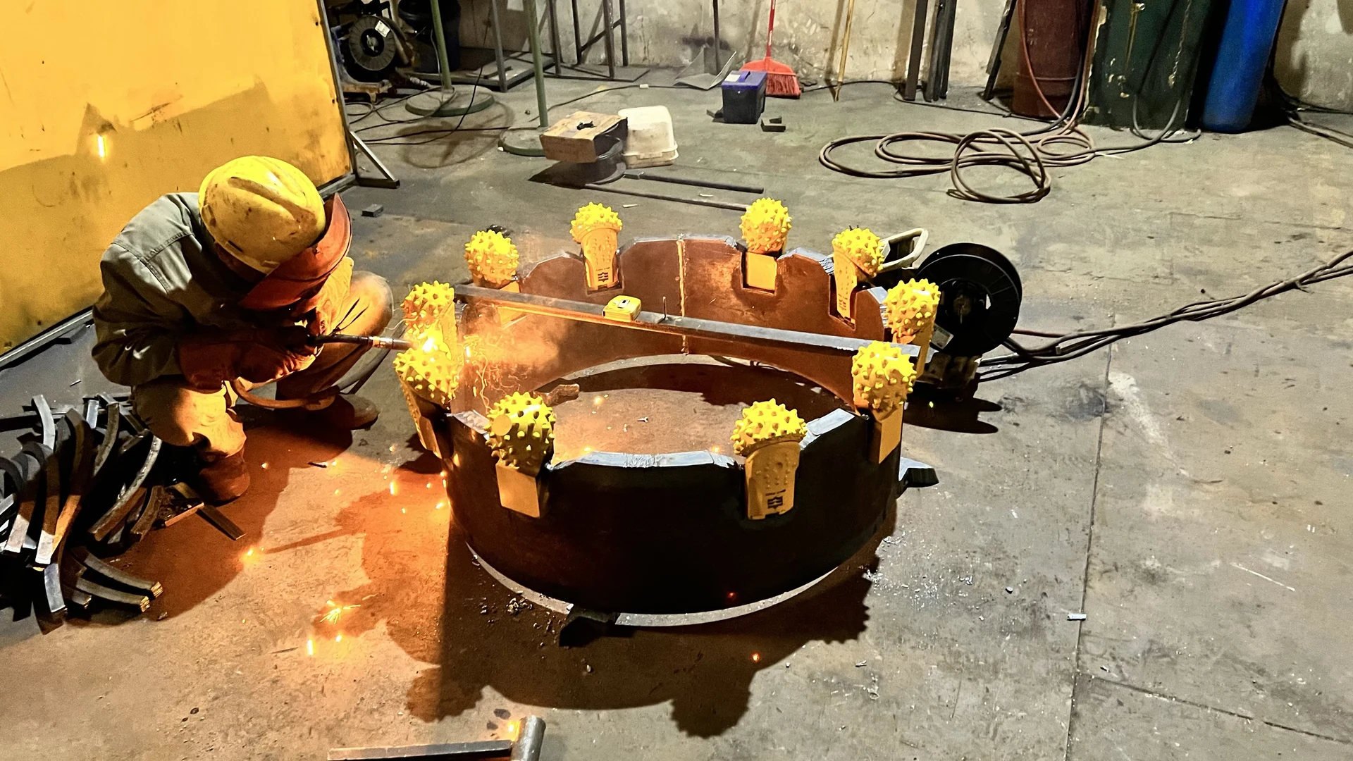
A weld-on choice also requires suitable positioning and welding controls. The checks below protect both the joint and the assembled bearing. Use the selected drawing, qualified welding procedure and assembly limits; see the installation guide for the photographed positioning sequence.
| Step | Work to complete | If it is missed |
|---|---|---|
| 1. Prepare the joint | Remove old weld, slag, rust, oil and paint from the intended joint and work-clamp contact. Dry-fit the leg against the specified opening; do not bridge an oversized cut-out with an improvised filler. | Poor seating changes the cutter position; contamination can contribute to pores, inclusions or poor fusion. |
| 2. Establish the current path | Connect the welding work-return clamp to clean bare metal on the stationary component being welded, close to the joint. Keep the return path out of the cone and bearing contacts. | Current crossing a bearing contact can cause local electrical erosion, separately from heat damage. |
| 3. Tack the complete layout | Set the centre and reference plane. Position the first inner and outer bits, tack them, then tack and measure the whole set before final welding. Recheck the centre after moving the barrel. | A tilted first bit or displaced centre can be copied around the ring and locked in by final welding. |
| 4. Distribute the weld sequence | Follow the specified run sequence across the assembly. The workshop method alternates portions of weld between positions instead of finishing one leg continuously. Remove slag between passes where the process requires it. | Local heat accumulation and contraction can shift the layout and heat the bearing assembly. |
| 5. Measure the relevant temperatures | The welding procedure must state steel preheat and interpass limits; the bit manufacturer must define any separate assembly-temperature limit and its measuring point. Take readings before the next run. | A satisfactory weld temperature at the joint does not establish a safe temperature at the seal and lubricant. |
| 6. Cool and recheck | Use the specified cooling method. After the assembly reaches the stated inspection condition, clean and inspect the welds, remeasure cutter positions and check cone movement. | Distortion, a changed cone feel or a visible weld defect may otherwise reach the first drilling shift. |
Fill in the controls before welding: process and consumable; current (A); voltage (V); wire feed (m/min), where applicable; travel speed (mm/min); preheat/interpass limits (°C); assembly-temperature limit and measuring point; pass sequence; cooling method. These values come from the applicable procedure and assembly design. An unspecified “low current” or a wet cloth is not a measurable temperature control.
Technical references: Miller on joint preparation, SKF on electrical bearing damage, and TWI on tack welding and weld sequence.