
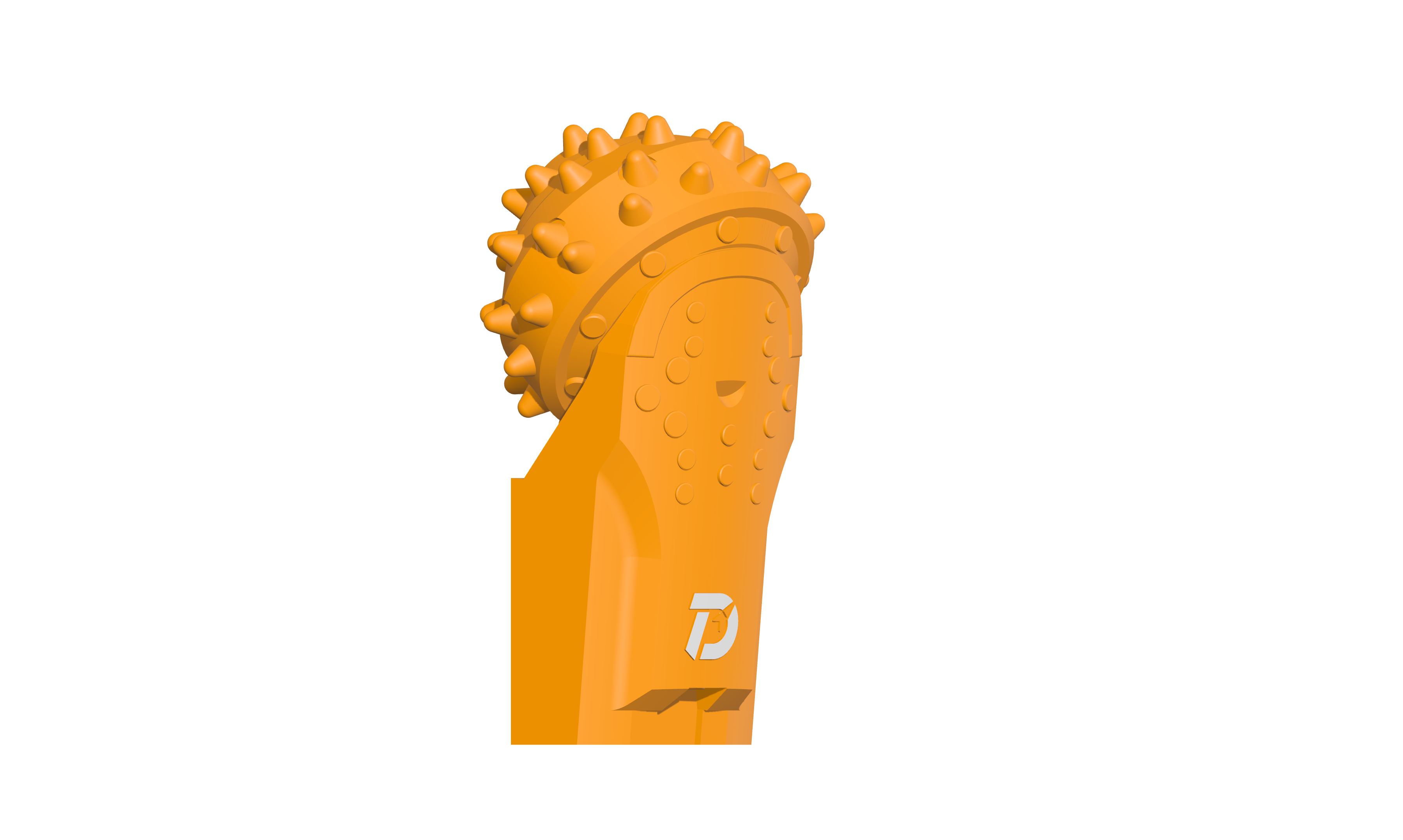
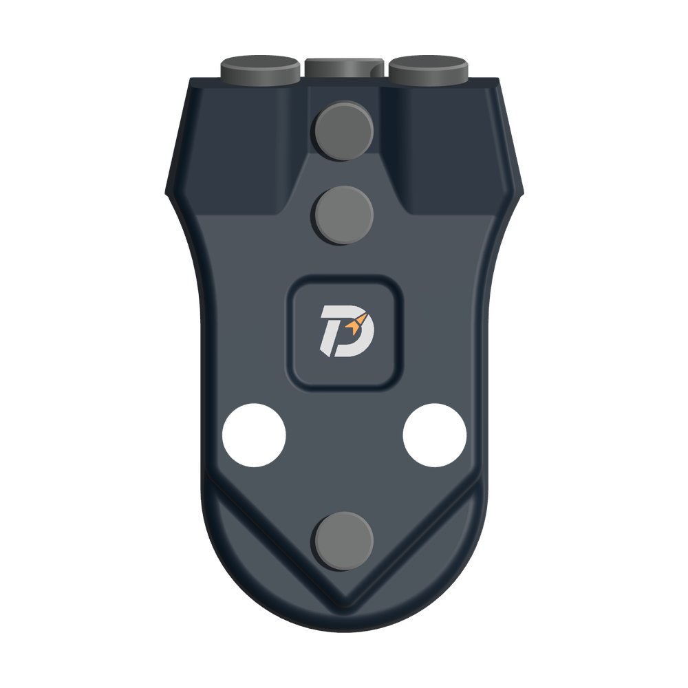
 WS39 casing tooth
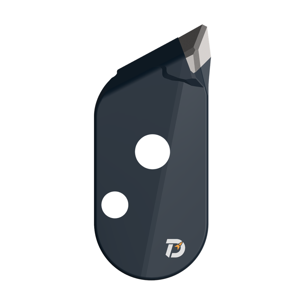 JM cutter tooth
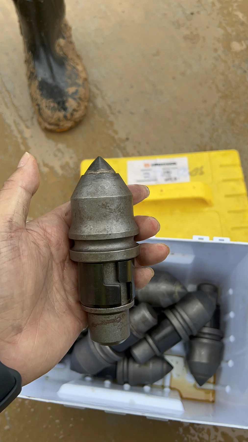
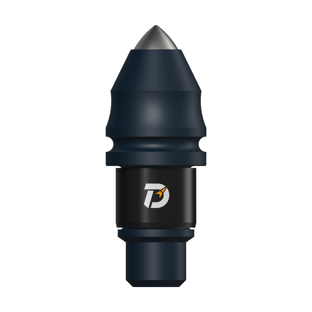 B47K22 bullet tooth
Assess bullet-tooth wear by position and inspection time, including the holder and surrounding cutting arrangement. A worn tooth shows the condition at inspection; it does not, by itself, identify the cause or establish service life.
What was installed at the start?
Record the tooth reference and starting condition before installation. Number the positions and photograph the body, carbide and seating area from repeatable angles.
At each inspection, distinguish a flattened or rounded tip from a broken tip or an empty insert position. Also record uneven body wear, holder-edge damage and retention condition.
Did the cutting set change during the trial?
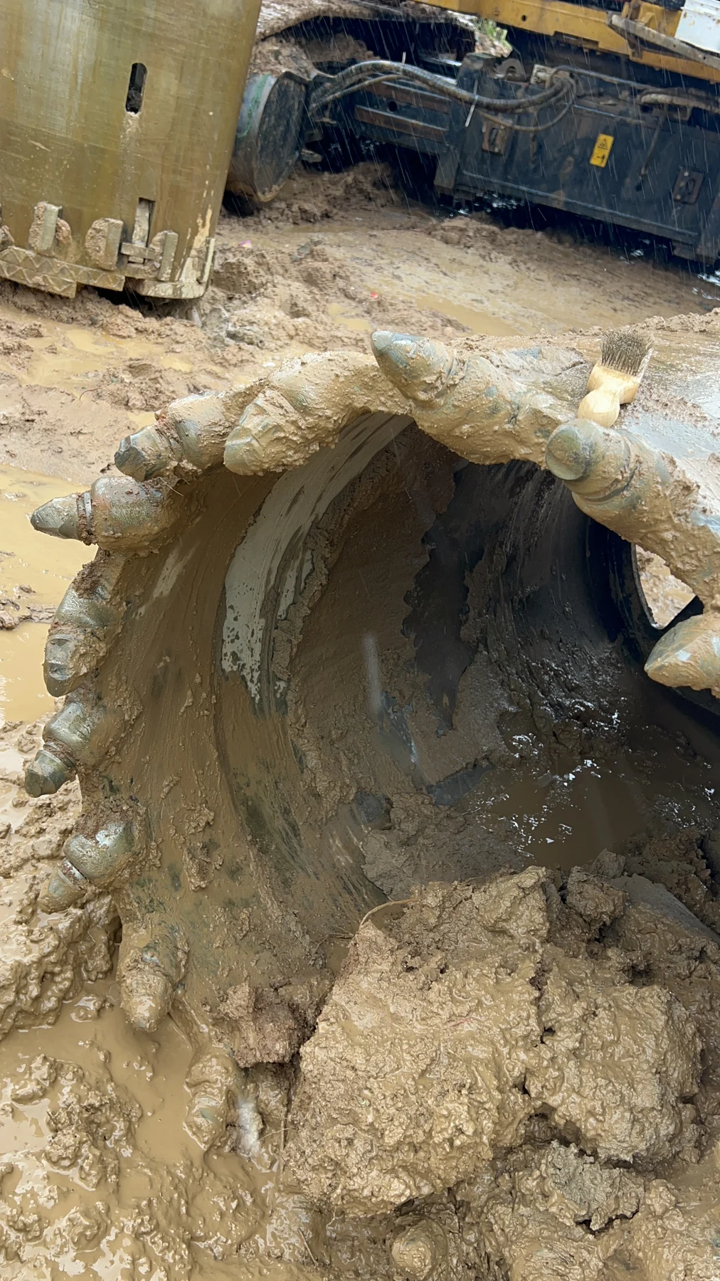
Take a full-ring photo before close-ups and log which numbered teeth were changed. Where tooth types or wear stages are mixed, keep each position’s history separate.
The Qingdao record includes a mixed cutting set on the following day. That arrangement cannot support a controlled like-for-like life comparison.
What should change at the next inspection?
| Observed feature | Inspect immediately beside it | Practical next action |
|---|---|---|
| Tip rounded or flattened | Remaining carbide, steel-body exposure and the holder’s leading edge. | Apply the agreed wear/replacement criterion before the holder becomes the leading contact. Photograph the retained or replaced condition at the same position. |
| One side of the body wears faster | Tooth seating and intended rotation, packed spoil, holder angle and the matching teeth in that row. | Clean and examine the tooth-holder interface and local obstructions using the tool’s maintenance procedure. Compare like positions; do not correct asymmetry only by replacing one tooth type. |
| Carbide is broken or missing | Remaining carbide, recovered fragments and the surrounding body support. | Keep the fragment with its position and interval. Use the prescribed hole-cleaning sequence before continuing so loose hard fragments are not repeatedly recut. |
| Holder edge is polished, chipped or wearing | Tooth projection, body loss, seating and adjacent cutting paths. | Inspect the holder before inserting another tooth. Restore or replace a damaged holder to the selected repair/fit requirements. |
Keep the comparison usable: record the tooth reference and replacement time for each position. A fresh tooth beside an old tooth starts with different exposure; a mixed set needs separate position histories before comparing wear.
After repeated repairs, check the mounting reference
The holder-edge check also depends on the structure carrying the holder. A separate rotary drilling bucket repair record described an original tooth plate that had been largely cut away during repeated repairs. Installing fresh teeth or holders does not, by itself, establish that the original mounting arrangement has been restored.
Before judging the replacement assembly, identify the remaining plate, its intended support for the holder and the valid datum specified for that repair. An edge left by cutting away old material must not automatically be treated as the original reference. Recheck the holder orientation from the applicable design reference under the manufacturer’s repair and acceptance procedure.
That record supports reviewing the repair scope. It does not demonstrate a measured angle change, a confirmed failure cause or a successful adjustment.
Reading spacing when reviewing neighbouring wear
The holder-edge check above includes adjacent cutting paths. Before comparing worn positions, distinguish two distances that can describe the same pair of teeth. In Kong Shuangteng’s two-tooth simulation, the separation across adjacent cutting paths was varied while the front-to-back separation in the cutting direction was kept fixed. The first tooth cut before the second. This third-party model explains the measurement terms; it does not establish the cause of wear in the Qingdao trial above.
Cutting direction →
Working points: 1 leads · 2 follows.
| Measurement | Direction and endpoints | What it tells you |
|---|---|---|
| A · Across the cutting paths | Between the reference lines of the two paths, perpendicular to cutting travel in the simplified plan view. | How far apart the adjacent passes act on the rock. |
| B · Along the cutting direction | Between the projected tooth positions, parallel to cutting travel. | How far the following tooth trails the first. |
The distinction matters because adjacent cuts can interact. In the study, closely spaced passes cut overlapping rock volumes; with greater separation, a rock ridge could remain between the paths. That balance also depends on the tooth geometry and cutting depth. Neither a shorter distance nor a lower force on the following tooth alone establishes the best complete layout.
On the actual barrel drawing, identify the tooth working points, path radii and positions around the ring. Keep those references with the measured values. A gap between holder edges is a different measurement, and a straight-path model does not provide a universal holder spacing, installation angle or acceptance tolerance.
Source: Kong Shuangteng, 旋挖钻机筒钻截齿破岩仿真研究, master’s thesis, China University of Geosciences (Beijing), 2021, §§4.1–4.2, pp.49–55. This is a reading aid based on a third-party simulation, not a DRILLNOVA performance test or an installation specification.