

 WS39 casing tooth
 JM cutter tooth
 B47K22 bullet tooth
Measure the body and mounting features, inspect the carbide joint, then check the matched holder. These two historical JM samples illustrate the method. Their readings are not acceptance dimensions for current catalogue parts; the drawing match remains unconfirmed.
Start with the five measured features
Clean the contact faces, check caliper zero and identify the sample. Re-seat the jaws and repeat with light contact at the same points.
Sample 1 records 153 mm overall length. Compare the same endpoints on the selected drawing.
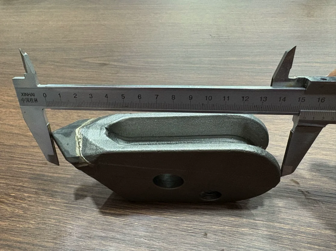
Five features, two recorded samples
| Feature | Sample 1 | Sample 2 | Measurement and fit implication |
|---|---|---|---|
| Overall length | 153 | 153 | Measure between the stated end faces; seating depth also affects installed projection. |
| Body width | 38 | 38 | Use corresponding body faces, clear of burrs and braze residue. |
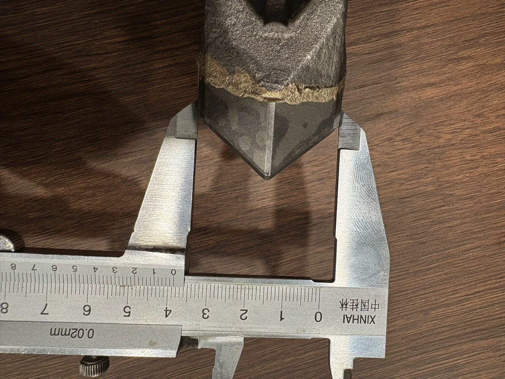
| Carbide-head span | 38.5 | 38.8 | Measure across the shaped head at the same height; this is a span, not a pin diameter. |
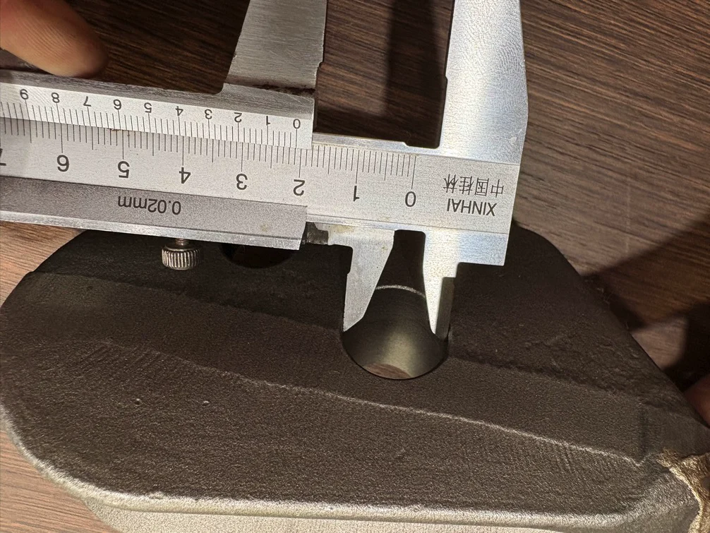
| Larger hole | 21 | 21 | Measure the bore and confirm its location separately from the retention-part size. |
| Smaller hole | 16 | 16 | Confirm diameter, spacing and orientation against the holder interface. |
Sample difference: 38.8 − 38.5 = 0.3 mm across the carbide head.
The 0.3 mm sample difference is not a drawing tolerance. Re-measure at the same height before comparison. Equal integer readings elsewhere do not establish zero variation below 1 mm.
Keep carbide measurement points consistent
The shaped head tapers. Moving the jaws changes the measured span, so compare at the same height.
Check carbide position, chipped or cracked edges, lift and movement at the joint. Hold a loose or visibly cracked head for assessment before installation.
Check the bores and the complete mounting
Measure beyond the chamfer with the jaws square to the bore axis. Check another direction if ovality is suspected; use the specified bore gauge where the tolerance requires it.
Clean the holder and check seating, rocking, hole alignment and retention. A 21 mm or 16 mm hole reading alone does not establish holder or pin fit.
Inspect the joint surface and section
Clean the carbide, copper shim and steel contact faces before brazing. Contamination can prevent wetting. Clean the completed joint by the specified method before inspection.
Inspect the full visible joint for interrupted filler, cracks, lift, pores and carbide position. A prepared section reveals the joint interior at the selected cut plane.
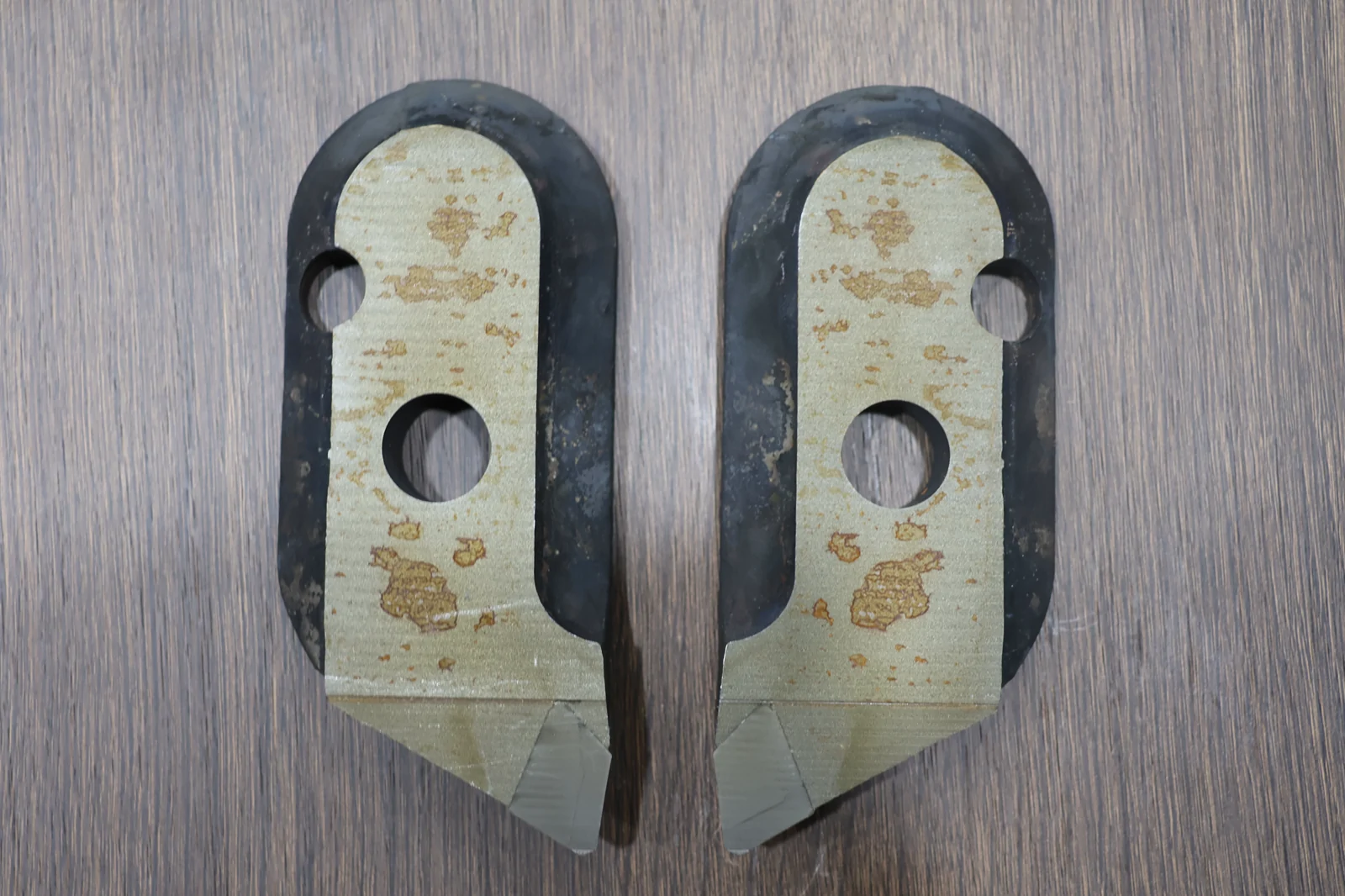
Joint inspection and follow-up
| Check | What to look for | Decision or next test |
|---|---|---|
| Carbide and body before brazing | Clean contact faces, correct carbide orientation and the specified shim/joint fit. | Correct contamination or misplacement before heating. |
| Cleaned external joint | Cracks, discontinuous fillet, missing filler, erosion, lifted edge or loose carbide. | Identify and hold the affected part for assessment against the joint requirements. |
| Prepared section of an identified sample | Filler distribution, internal voids, poor flow or local erosion at the cut plane. | Assess to the specified method; add sections or tests if the plan requires them. |
| Body hardness, where specified | Test location, HRC scale, individual readings and surface condition. | Historical JM plan: 42–46 HRC for the steel body. This is a requirement, not a measured result or carbide hardness. |
Visual inspection does not reveal all internal voids. Section results cover the sampled part and plane; batch coverage follows the agreed test plan.
Method references: Mitutoyo caliper guidance and Lucas-Milhaupt brazing fundamentals.