
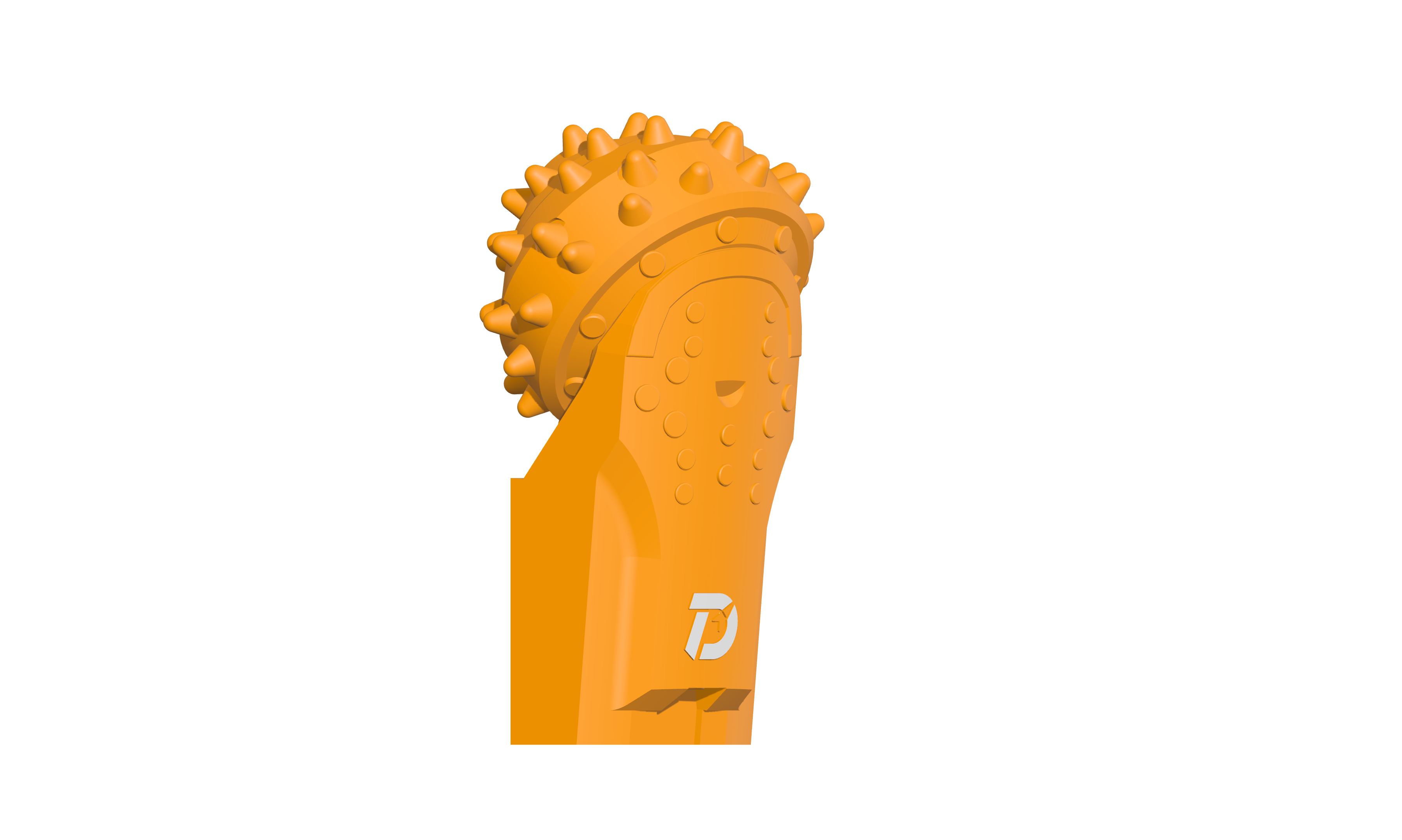
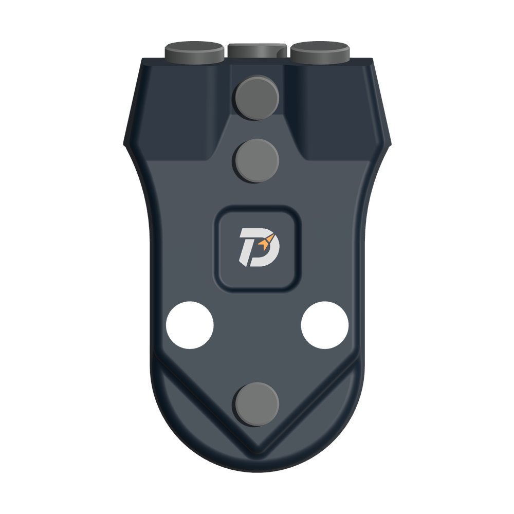
 WS39 casing tooth
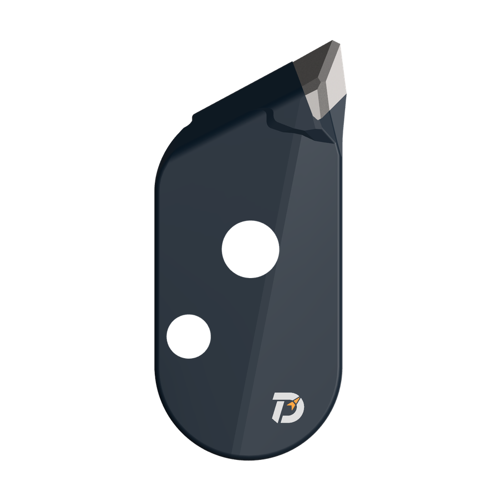 JM cutter tooth
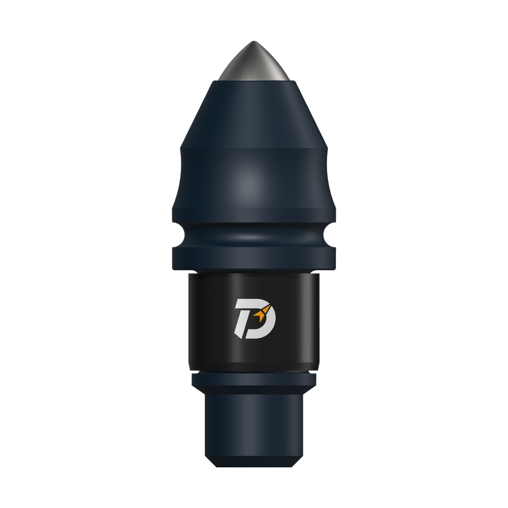 B47K22 bullet tooth
A staged core barrel can have a larger cutting section above a smaller guide section. A label such as “2.0 × 1.5 m” may describe those two diameters, rather than diameter × height. Read the dimension lines and the preceding hole together before comparing tools.
Two diameters are not a diameter and a height
Wei and Yang’s published bridge-pile example describes an upper 2.0 m roller-bit barrel with a lower 1.5 m guide head, followed by an upper 2.5 m barrel with a lower 2.0 m guide head. The smaller lower section corresponds to the preceding hole. These are the authors’ project configurations, not standard sizes to copy. The table isolates two enlargement assemblies; it is not the complete construction sequence.
| Tool stage | Larger upper section | Smaller lower guide |
|---|---|---|
| 2.0 × 1.5 m | 2.0 m enlargement | 1.5 m, corresponding to the preceding bore |
| 2.5 × 2.0 m | 2.5 m enlargement | 2.0 m, corresponding to the preceding bore |
Barrel height is a separate dimension. These paired sizes also differ from the inner and outer cutting paths of one cutting ring.
Why can one drawing show three diameters?
The three measurements below refer to different parts of the same enlargement sketch in Wei and Yang’s paper. The table identifies each measurement’s object and endpoints.
| Measurement | Reference in the example | Measurement endpoints |
|---|---|---|
| 2.5 m | Upper hole | Across the two walls of the wider upper hole. |
| 2.0 m | Current cutting section | Across the larger section of the enlargement tool. |
| 1.5 m | Earlier smaller hole | Across the lower pilot hole; the written example pairs this with the lower guide. |
This table identifies what each measurement refers to. It does not represent the tool profile, guide clearance or construction depths; the rows do not show vertical spacing.
What this changes: the 2.5 m upper-hole dimension does not make the guide 2.5 m wide. For the 2.0 × 1.5 m assembly, ask for the cutting-section and guide dimensions separately. Keep barrel height on a separate axial dimension line.
Upper stabilizers and lower guides use different reference positions
A guide’s position changes which part of the existing hole it relates to. These two arrangements come from separate published examples; they are not interchangeable parts or a combined DRILLNOVA design.
| Arrangement | Where it sits | What to identify on the drawing |
|---|---|---|
| Upper stabilizer · Wang example | Between the smaller first-stage barrel and the Kelly bar. | The wider upper hole around the stabilizer, separate from the smaller cutting section below. |
| Lower guide · Wei and Yang example | Below the larger enlargement section. | The smaller hole already drilled below the current cut, corresponding to the lower guide. |
“Guide” does not mean “toothless”. Wang describes roller bits on the outer barrel and bullet teeth on an inner component. That is a feature of Wang’s assembly, not evidence of the teeth fitted to Wei and Yang’s guide. Identify the actual toothed parts before substituting a smooth guide sleeve.
Start with the hole that already exists
These examples concern large-diameter rock-socketed piles enlarged in stages. Their shared drawing question is how the next tool relates to an existing smaller bore. For first entry into rock, that smaller bore may not yet exist; the first-stage guidance arrangement therefore needs its own explanation.
Guide geometry alone does not establish a complete drilling cycle. The two papers describe different companion-tool and cleaning sequences. Identify core recovery and cleaning separately for the selected project, along with ground conditions, rig capability and the approved construction method.
One centre or several smaller holes?
Several smaller holes inside a large pile are not the same layout as a larger barrel working above a smaller lower guide. Li and colleagues’ published “plum-blossom” example describes cutting around the perimeter, then making smaller core-barrel holes—generally three in a triangular arrangement near that perimeter. Spoil removal and finishing are separate parts of the described cycle.
| Layout | Relationship to read | Information needed |
|---|---|---|
| Concentric staged enlargement | The smaller preceding bore and the larger current cut share a centre. | Previous bore diameter, next cutting diameter and guide position. |
| Several smaller core holes | The smaller holes occupy different positions within the outer cutting perimeter. | Hole count, each hole’s diameter and centre position relative to that perimeter. |
A label such as 2.0 × 1.5 m does not specify a multiple-hole plan: it provides no hole-centre positions or spacing. For that plan, mark the smaller holes and the outer cut in plan view, identify the depth interval, and explain how the remaining rock and cuttings will be removed. The cited description does not establish a universal spacing or a method to adopt for your site.
Source: Li Yaoliang, Chen Yigui, Huang Lei and Luo Yunfeng, 大直径超深、超厚嵌岩旋挖灌注桩梅花形成孔施工技术, Building Construction, 2020, 42(3), 310–312, §2.2. DOI: 10.14144/j.cnki.jzsg.2020.03.004. This is a third-party method description, not a DRILLNOVA project or performance claim.
Published sources and scope
This is a reading guide to third-party published designs. The projects and tool configurations below are not presented as DRILLNOVA supply or field performance.
- Wei Chaoxi and Yang Yong, 大直径嵌岩桩旋挖钻成孔技术改进及应用, Guangdong Architecture Civil Engineering, 2021, 28(5), 112–115; §3.5 and Figure 5. DOI: 10.19731/j.gdtmyjz.2021.05.028.
- Wang En, 大直径深长嵌岩桩分级成孔技术研究与应用, Urbanism and Architecture, June 2021, vol. 18, 141–143; §§5.1 and 5.3, Table 3. DOI: 10.19892/j.cnki.csjz.2021.18.40.
The numerical examples explain labels and component relationships. They are not operating settings, universal stage sizes or a promise of drilling rate or verticality.