

 WS39 casing tooth
 JM cutter tooth
 B47K22 bullet tooth
Start with the ground interval, required cutting paths and rig connection. Review cutting, core recovery and cleaning together before selecting a core-barrel configuration.
01
Describe the rock interval
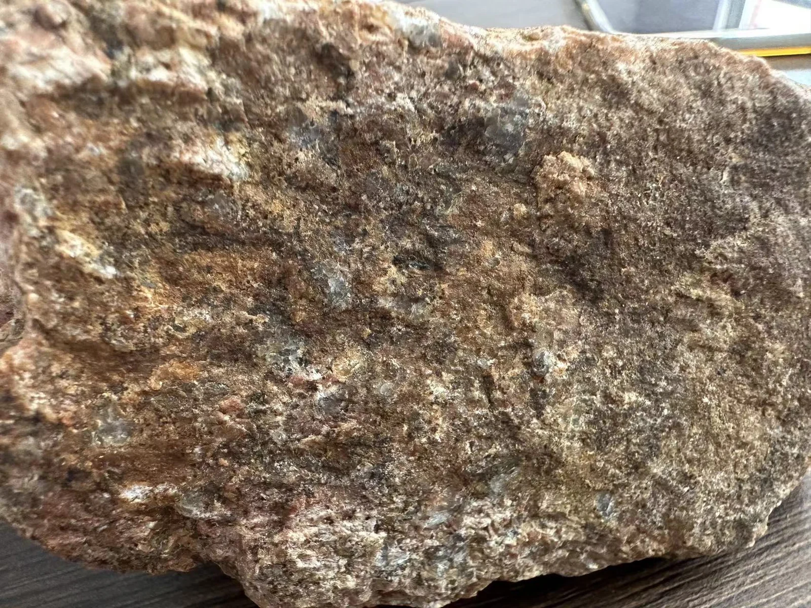
Provide the formation by depth, available rock-test results and the ground actually encountered. A photograph adds useful context, but it cannot establish compressive strength by itself.
02
Match the complete tool to the job
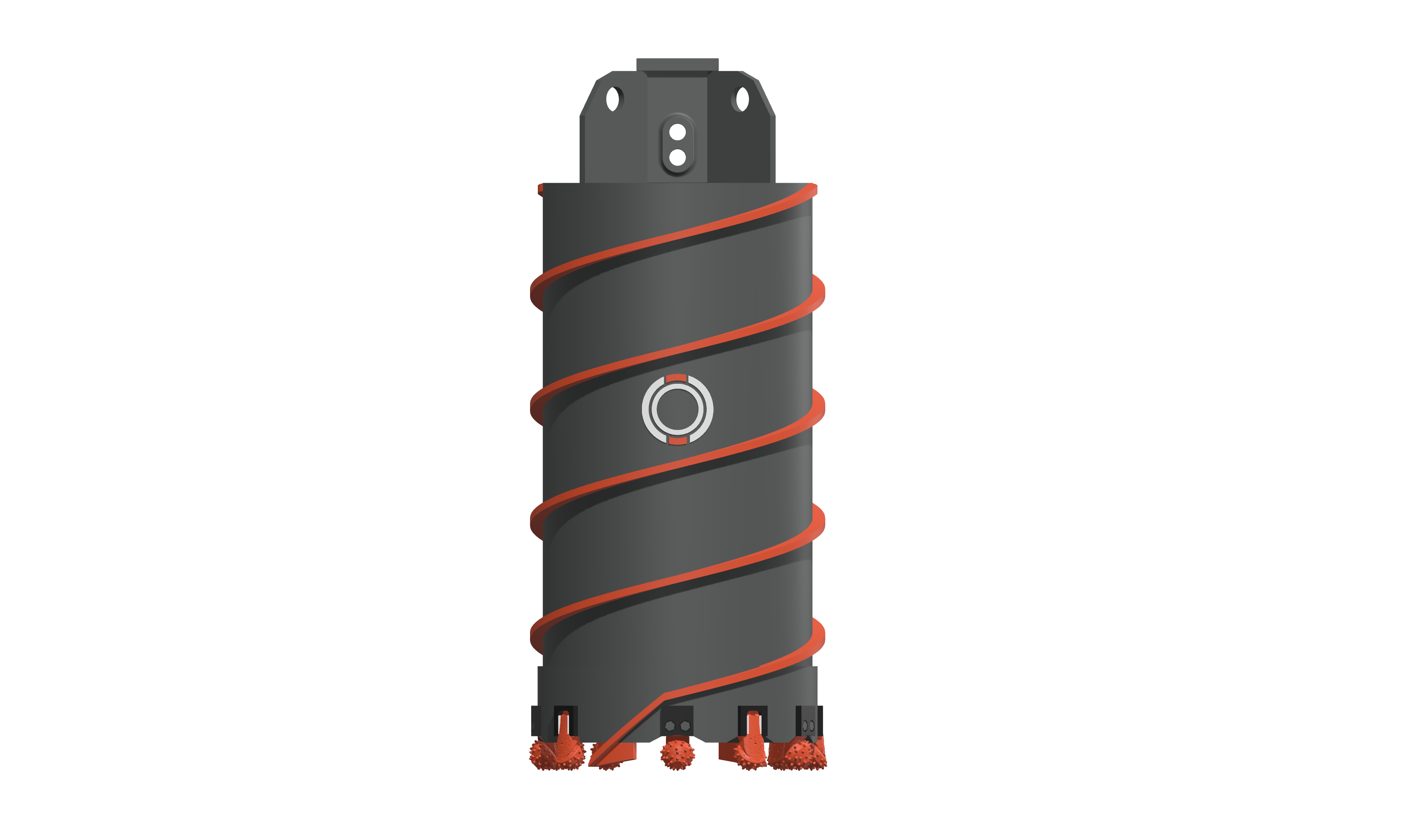
Compare the required hole diameter, steel cutting ring and inner and outer cutter paths. Include rig-connection dimensions and the tools used for breaking or recovering the core.
Compare the roller-bit and bullet-tooth arrangements with the ground and rig capability. Include how the core is broken and recovered, how the hole is cleaned, and which part of the present cycle needs to improve.
Check the rig before comparing configurations
Identify the rig, Kelly bar, selected gear and working mode before comparing configurations. The example below shows what to capture; its readings are not recommended settings. Use the load and RPM guide to interpret the operating record.
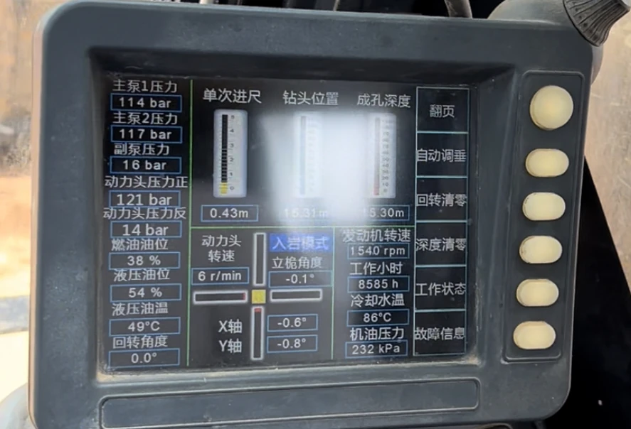
| Display item | Unit / context | Why it belongs in the record |
|---|---|---|
| Rotary-drive speed | rpm; actual value and selected gear | Distinguish working speed from engine rpm or a control setting. |
| Hydraulic pressure / crowd force | Keep the original label and MPa, bar or kN | A pressure reading is not a weight-on-bit value; conversion requires the rig’s circuit, effective areas and load path. |
| Torque and available limit | kNm where provided; Kelly configuration | Check the actual value together with the permitted limit for the selected equipment. |
| Kelly locking and crowd stroke | Indicated lock position / remaining stroke | Confirm the applicable engagement and stroke indication before advancing or lifting under the rig procedure. |
| Tool depth and time | m, timestamp and depth reference | Separate downhole position from new advance and from time spent clearing or recovering core. |
BAUER’s B-Tronic display guide and Liebherr’s Kelly assistance overview illustrate machine-specific pressure, torque, speed and locking indications. Use the manual for the actual rig to interpret its labels.
Define the performance question with a recorded interval
An 800 mm MH-3 field review recorded two windows on a Sunward 420. They show why depth and time should be retained alongside the operating notes.
| Window | Depth change | Elapsed time | Calculated window rate |
|---|---|---|---|
| 10:20–10:58 | 35.00 → 35.27 m | 38 min | 0.27 ÷ (38/60) = 0.43 m/h |
| 12:20–13:04 | 35.67 → 36.02 m | 44 min | 0.35 ÷ (44/60) = 0.48 m/h |
The recorded rotary speeds were 12 rpm and 15 rpm respectively, and the operating/clearing behaviour also differed. These are observed window rates, not isolated cutting rates or proof that increasing speed caused an improvement. See the complete field review.
Before lowering again, compare recovered material with the last interval, clear packed cuttings, inspect cutter rotation and damaged positions, and confirm the next core-recovery/cleaning step. When advance drops while loading rises, investigate the changed conditions before treating more pressure as the answer.