

 WS39 casing tooth
 JM cutter tooth
 B47K22 bullet tooth
Zengcheng · 1,200 mm rotary piling · June–August 2022
On-site MH-3 refit: more than 50 m of recorded drilling.
DRILLNOVA · Field report · Updated
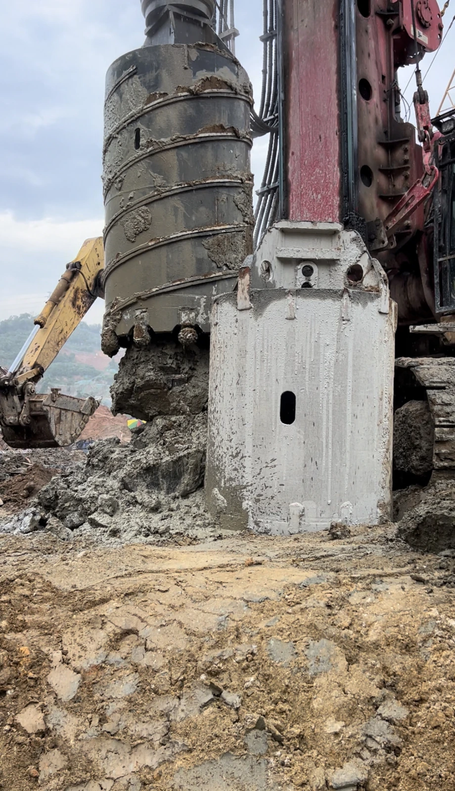
The customer’s original core barrel and roller bits were supplied by others. Faced with repeated cone loss and vibration, the customer invited our team to apply its drilling-tool experience on site.
We helped refit the existing barrel, guided cutter positioning and welding, trained the operators and followed the tool into service. The final follow-up recorded approximately 57 m of cumulative drilling with the refitted assembly.
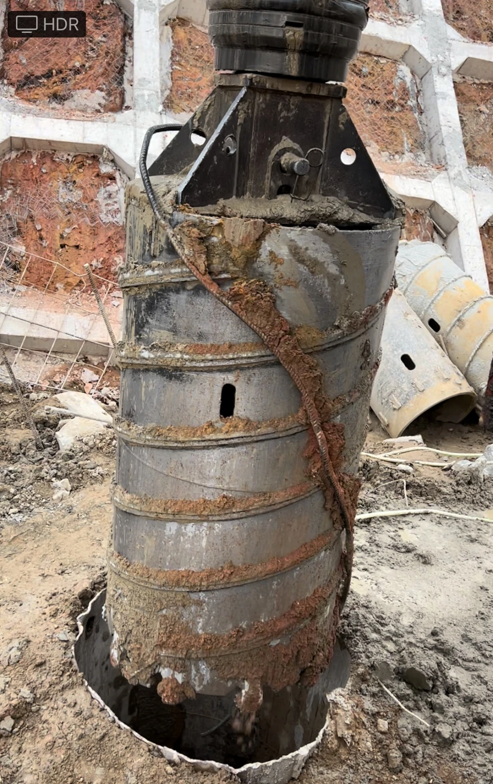
23–24 June · understand the existing tool and the problem
The customer asked us to assess a barrel and original roller bits that had not been supplied by our team. The operator reported repeated cone loss and increased vibration. Our assignment was to improve the use of this existing tool, starting with its geometry, the operating practice and the material around the cutters.
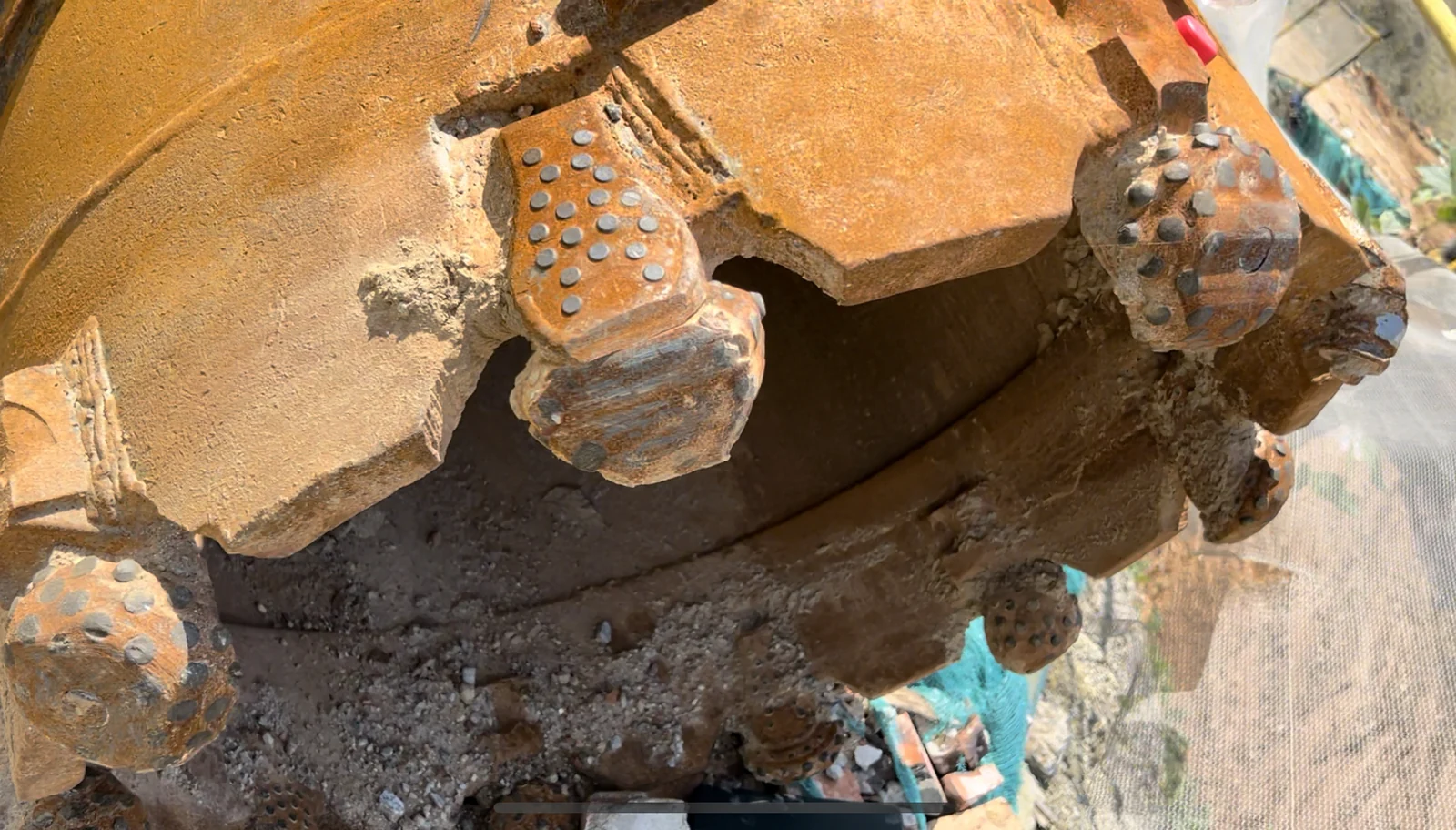
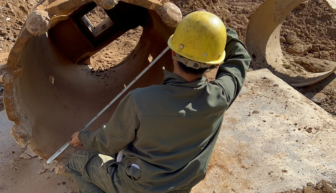
The nominal 1,200 mm barrel had ten roller bits and no scrapers. The initial notes recorded a 1,080 mm cutting-ring diameter, seized outer cutters, inner cone wear and uneven spiral wear. The ring dimension describes the steelwork, not the maximum cutting diameter.
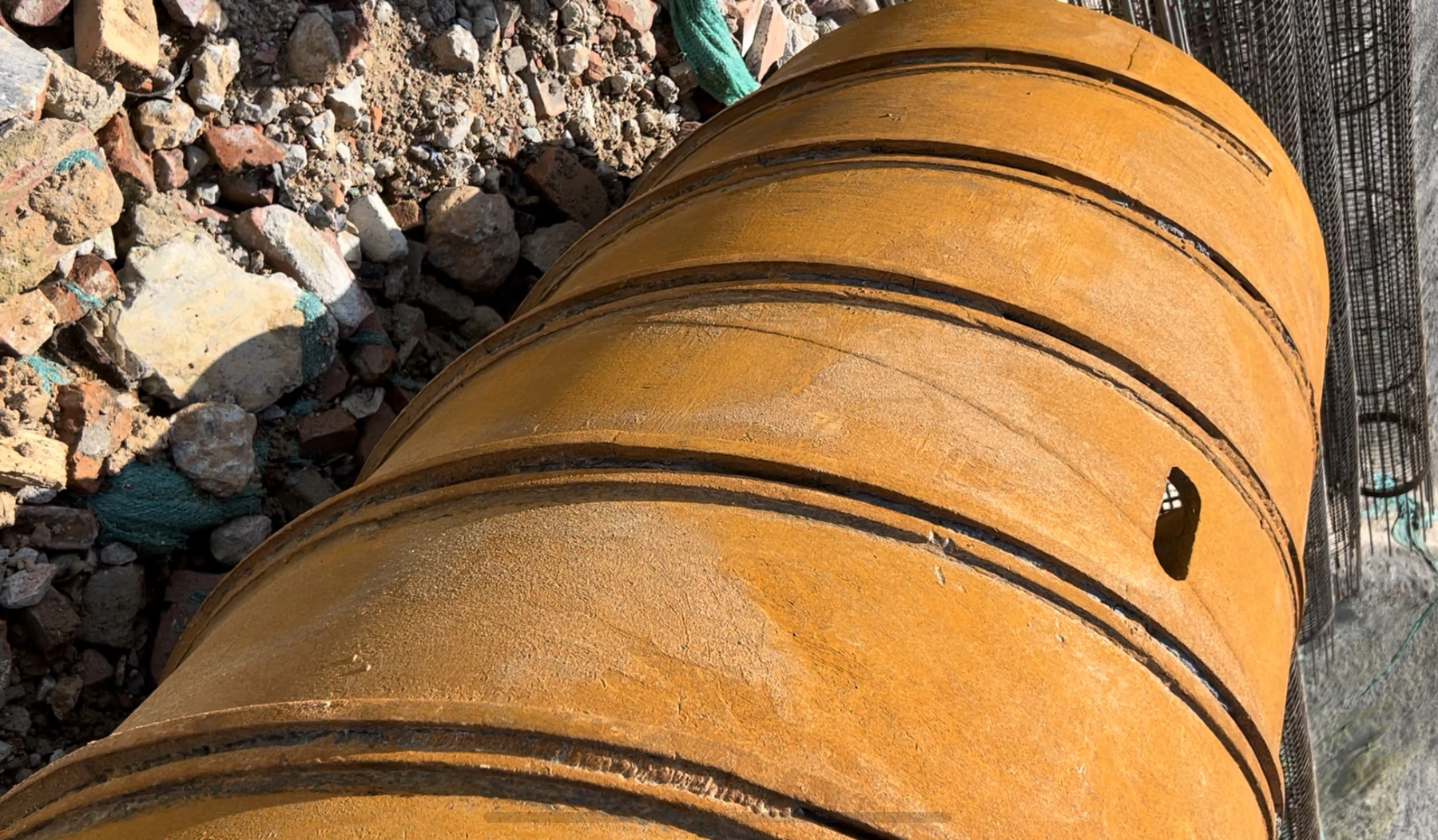
On 24 June, we measured the retained shell and the companion bullet-tooth barrel. The guide wear and the shell’s joined construction raised a question about alignment between the lower ring and the drive connection. That mattered before choosing a centre reference for the new cutters.
We also checked the recovered rock, the displayed operating parameters and the limited fluid supply. Packed cuttings, heat and the operator’s preferred speed/load were investigated alongside the tool geometry; the first visit did not establish a single cause for the missing cones.
Original tool, ground observations and survey dimensions
| Item | Recorded detail |
|---|---|
| Rig / nominal barrel | Sany 415R; 1,200 mm core barrel |
| Existing cutting ring | 1,080 mm diameter recorded at the initial visit |
| Original assembly | 10 roller bits; no scrapers |
| Refit configuration | 10 MH-3 roller bits + 4 scrapers; existing shell retained |
| Site work | 26–27 June 2022; cutouts/spacers prepared, centre set, cutters positioned and welded; spirals partly repaired |
The initial site feedback of 40–50 m concerned the old assembly. It is background to the refit, not a matched comparison with the later MH-3 work.
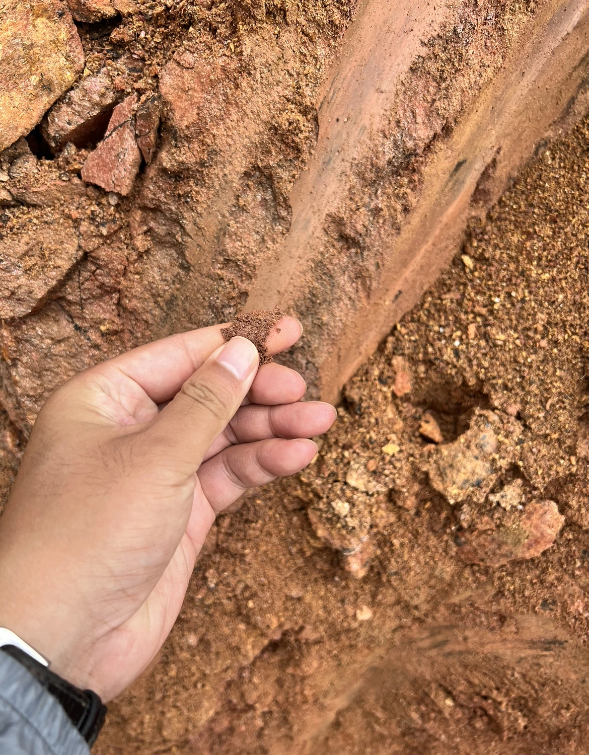
The first visit described the samples as monzogranite / granite-amphibolite and estimated 100–200 MPa; the 30 June notes described weathered mudstone through gneiss. These are dated field descriptions, not a laboratory UCS certificate or a verified uniform rock interval.
A refit plan for the customer’s existing barrel
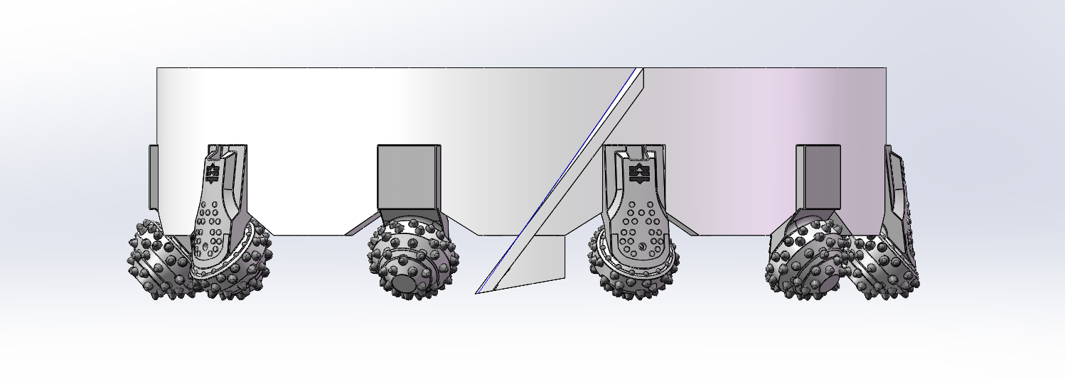
The initial plan retained the shell and specified ten MH-3 roller bits with four scrapers. Spiral-guide repair, operating adjustments and better mixing of cuttings with the drilling fluid were part of the same discussion.
| Site observation | Proposed response | What happened |
|---|---|---|
| Existing ten-cutter arrangement without scrapers | Fit ten MH-3 roller bits and four scrapers | Completed during the 26–27 June refit |
| Worn spiral guides and packed material | Restore guide height and improve material clearance | Only partial spiral repair was completed under site constraints |
| Vibration and uncertain operating conditions | Review entry speed, loading and fluid/clearing practice with the operator | Observed again during the 30 June–1 July runs; adjustments remained specific to the site |
On 25 June, the team arranged the scraper and spiral parts with the fabricator, booked the welder and coordinated the site equipment. The record distinguishes the original proposal from what could actually be built on site.
26–27 June · turn the plan into a fitted assembly
The welding record follows the job through preparation, fitting, positioning and completion. The critical checks happened before the final welds, while the cutter height and position could still be corrected.
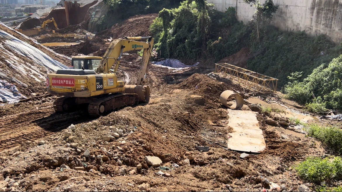
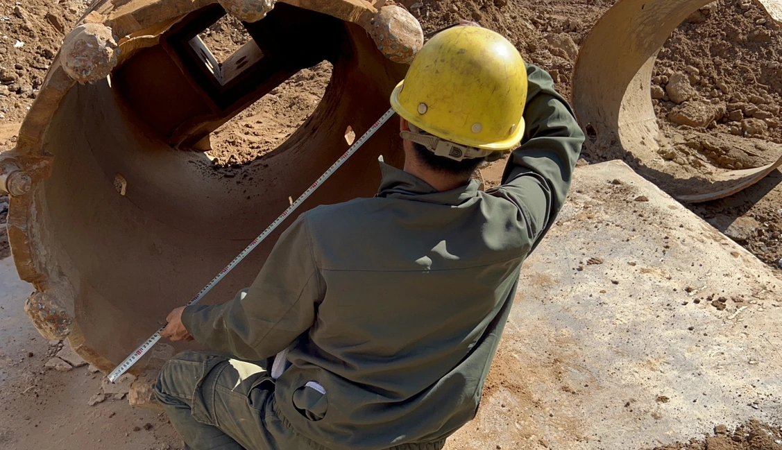
Prepare the opening and cutter projection
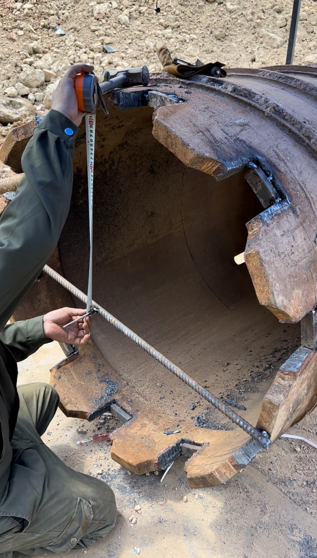
The crew cleaned the lower ring, checked its diameter and compared the old weld openings with the MH-3 leg. They then trimmed the openings, cut the spacers and rechecked the planned cutter projection before fixing the spacers.
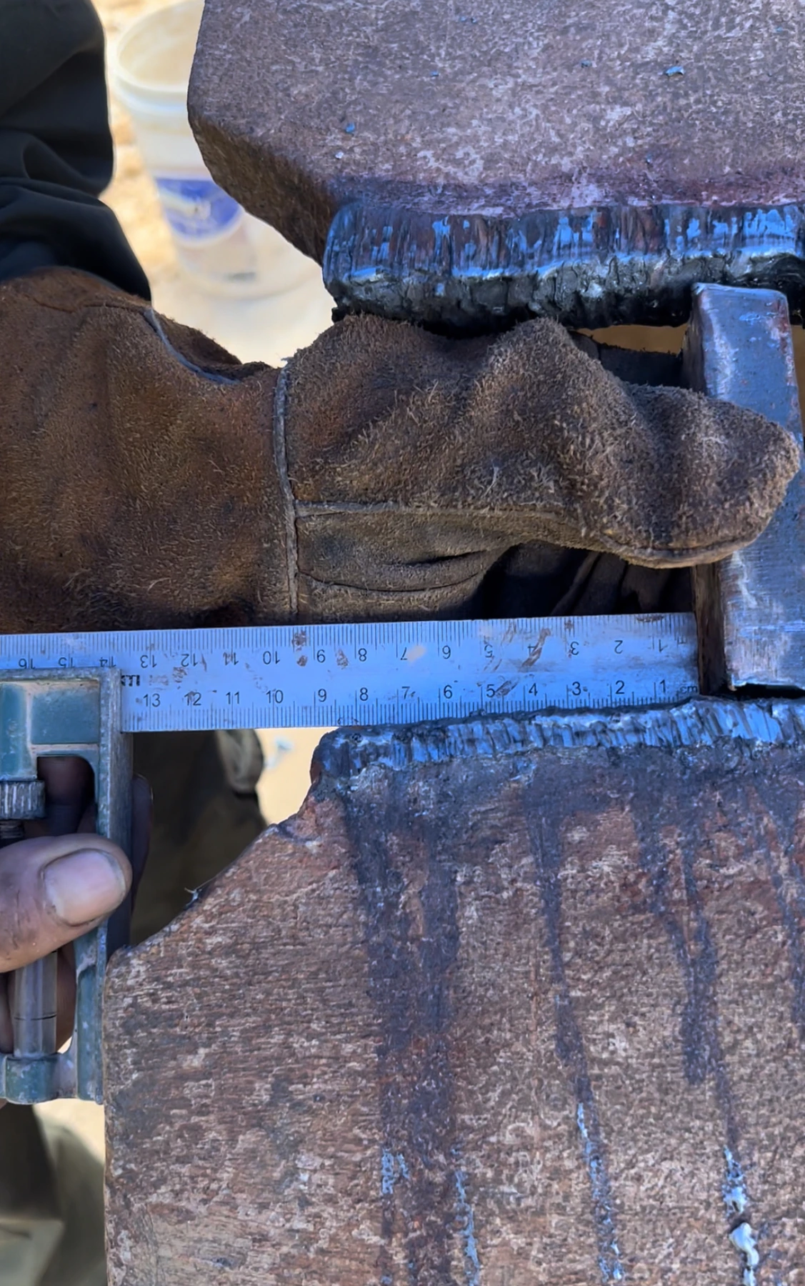
Establish the centre, then position and weld
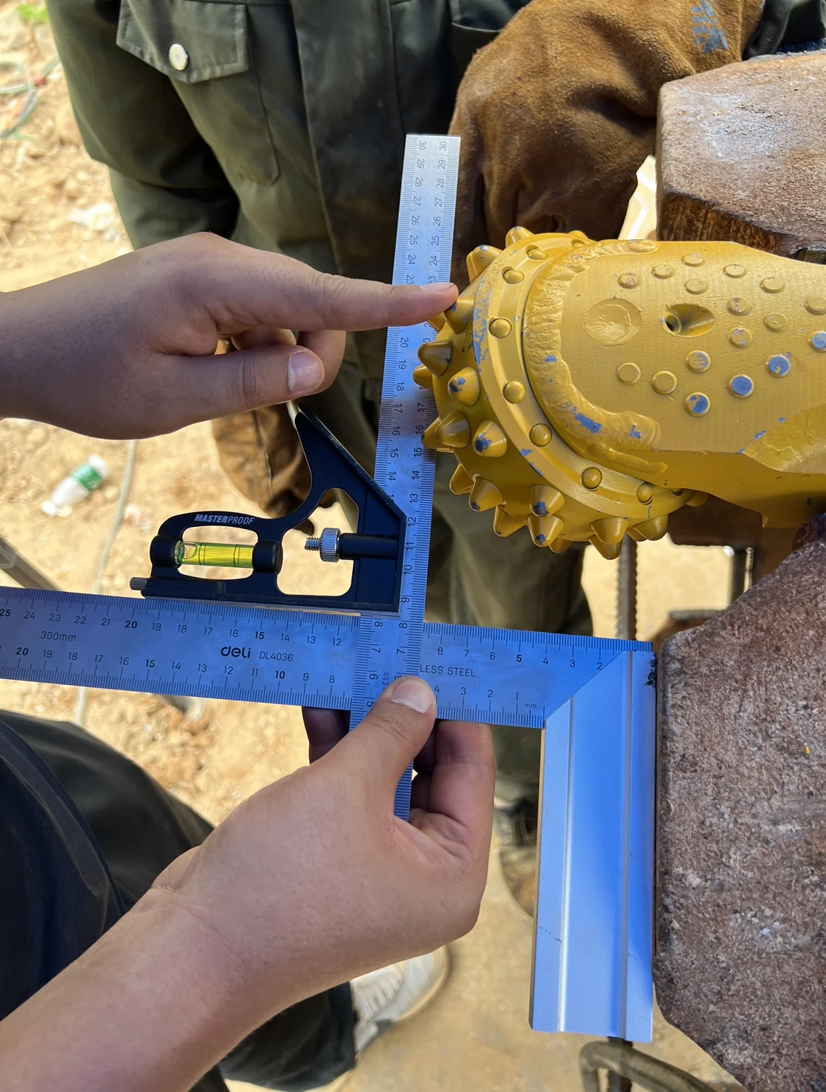
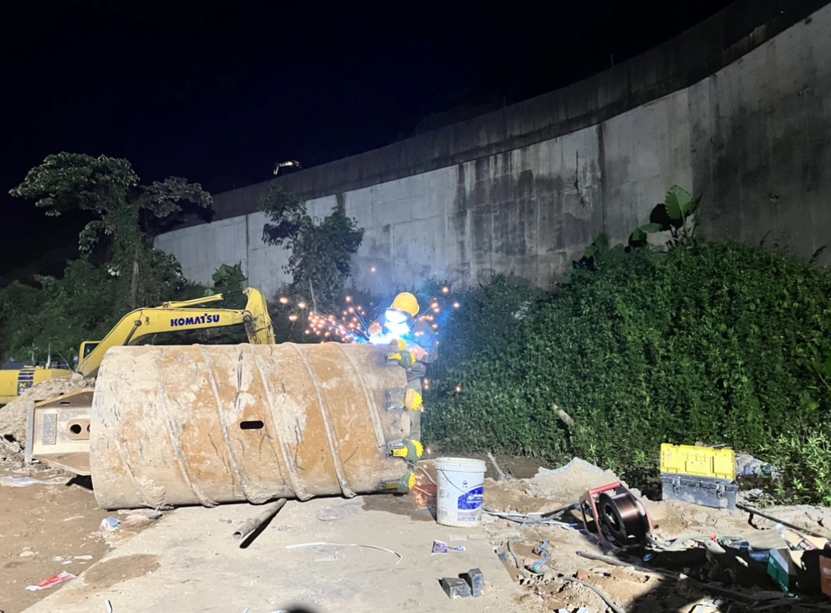
A steel-bar reference was used to locate the barrel centre. The team rechecked that reference, then controlled the design positions while the welder tack-fixed the roller bits. Full welding followed, with attention to heat transfer and cooling around the roller-bit assembly.
End-of-day condition: guide-strip work remained incomplete
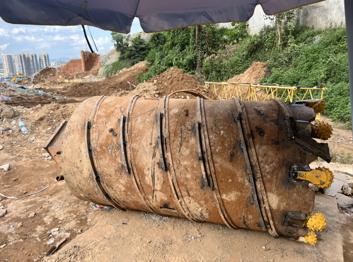
Power interruptions pushed the remaining work into 27 June. The new roller bits and scrapers had been fitted, but the guide-strip repair was still incomplete when the photograph below was taken. It records the end of that day’s work, not a fully finished barrel. Approximately 10 mm variation in scraper bevel cuts also prompted a proposal to agree the geometry and pre-cut parts in the workshop for the next job.
26–27 June: welding sequence and control-point record
| Time / date | Recorded work | Control point |
|---|---|---|
| 26 June · 08:27 | Prepare a level work area and steel plate | Provide a stable surface for rotating and positioning the barrel |
| 08:47–09:25 | Clean the lower ring and remove loose rust; measure its diameter | Assess the retained ring before cutting |
| 09:29–11:05 | Compare old openings with the MH-3 leg; plan projection; cut out old cutters | Check the opening size and the intended spacer height |
| 11:10–13:44 | Finish the openings, size and fix the spacers | Recheck the intended cutter projection |
| 13:50–14:22 | Establish the centre with the steel-bar reference | Team recheck before locating the cutters |
| 14:26–15:10; 17:34–19:27 | Position and tack-fix the roller bits | Welder places the parts; team checks the design positions |
| 19:29–20:12; 21:00–22:08 | Full welding | Monitor heat transfer and cooling around the roller bits |
| 27 June · 09:39–11:00; 12:08–16:11 | Fit scrapers and partly repair the spirals | Inspect bevel-cut consistency and heat exposure near the cutters |
Power interruptions occurred between the recorded working windows. The diary records cooling precautions, but does not provide a qualified welding procedure, welding temperature limits or a complete weld-acceptance record. Those must be agreed for the actual assembly.
30 June–1 July · follow the drilling and recovery cycle
The next visits followed the rebuilt tool back into the hole. The observations connected drilling, lifting, recovered material and cutter inspection, so the next adjustment could respond to what was happening at the working face.
Leave the operators with a usable method
The on-site work included practical training for the crew. We showed the team how to establish the centre reference and position the roller bits, then discussed entry, speed and loading, fluid supply, and clearing the cutting face with the operators. The incoming operator was also briefed so the operating approach could continue across the handover.
On 30 June, the operator recognised the effect of insufficient water on packed cuttings. The team discussed increasing fluid supply, reducing speed for the observed rock interval and clearing the cutters between advances. On 1 July, the log distinguished initial entry from stable drilling and recorded gentler re-entry after core recovery.
30 June · compare the operating response
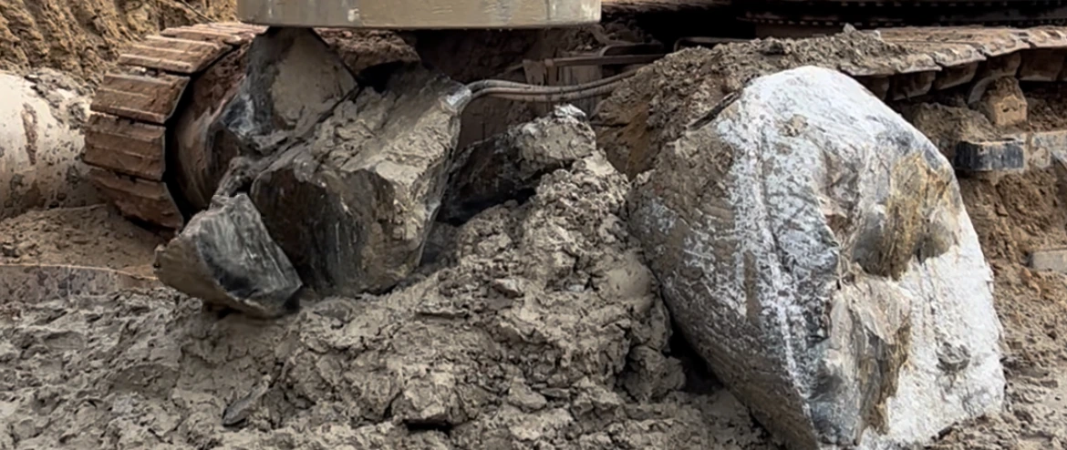
After about 1.2 m, the carbide inserts and legs remained in good condition, with light wear on the cone and its back. Relatively dry material was packed around the cutters. The team discussed fluid supply and clearing with the operator, alongside a lower-speed operating trial.
30 June: instrument photographs and two short operating windows
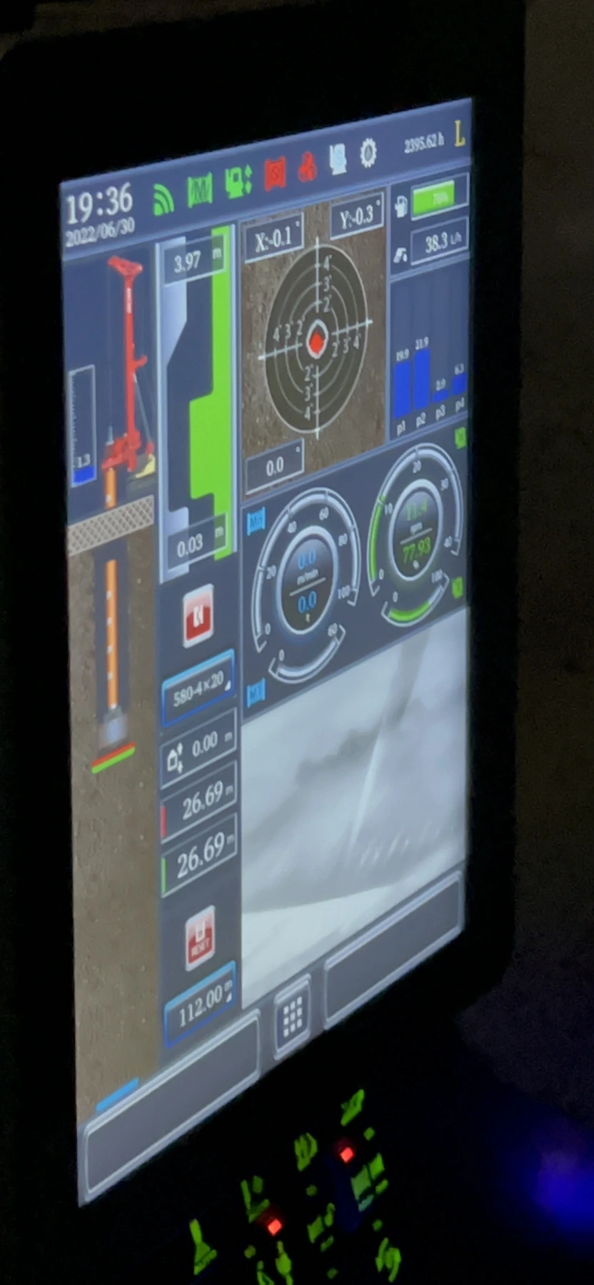
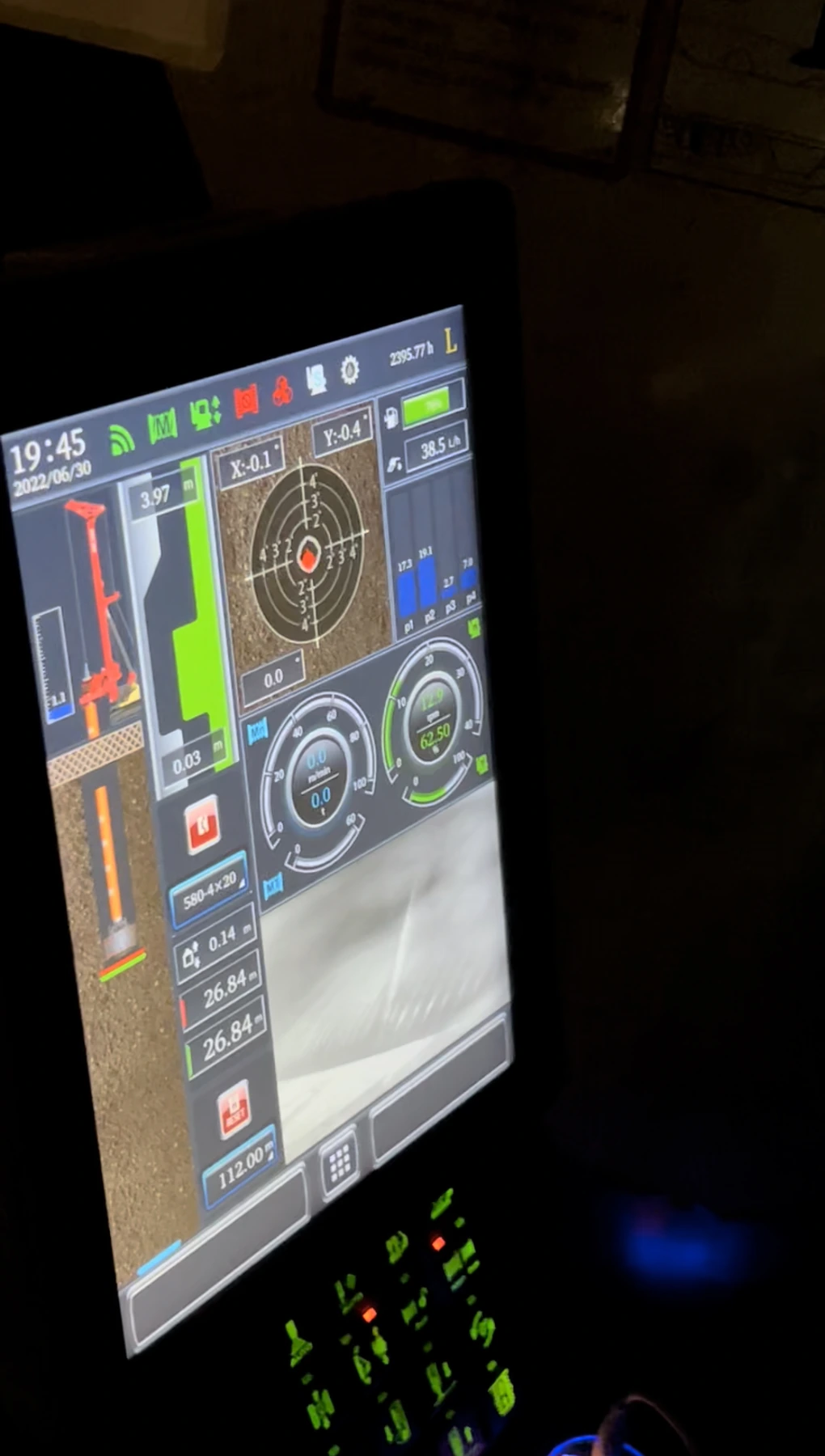
Each photograph belongs to a different observation below; the two images are not the start and finish of one timed run.
| Head speed | P4 channel reading | Recorded advance / elapsed |
|---|---|---|
| 11–15 r/min | 5.0–6.0 | 0.11 m displayed / 10 minutes |
| 8–10 r/min | 7.0–8.0 | 0.09 m / 6 minutes |
The first advance was also estimated at about 0.12 m; the table retains the displayed 0.11 m. The two windows are site observations, not a controlled productivity test. P4 is a machine-display channel; the diary’s estimated total tonne loads were not calibrated as force at the cutters.
What rock was encountered?
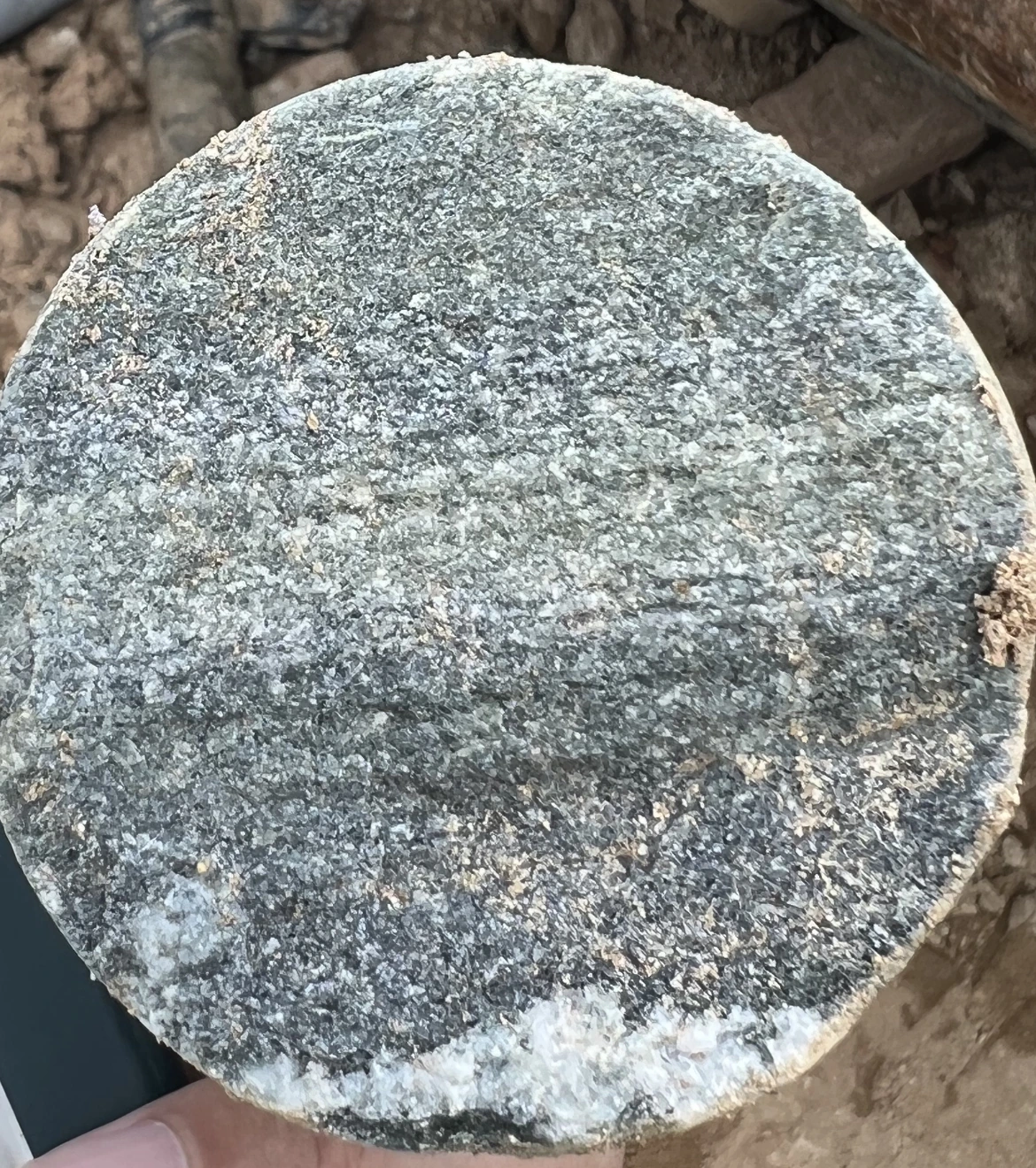
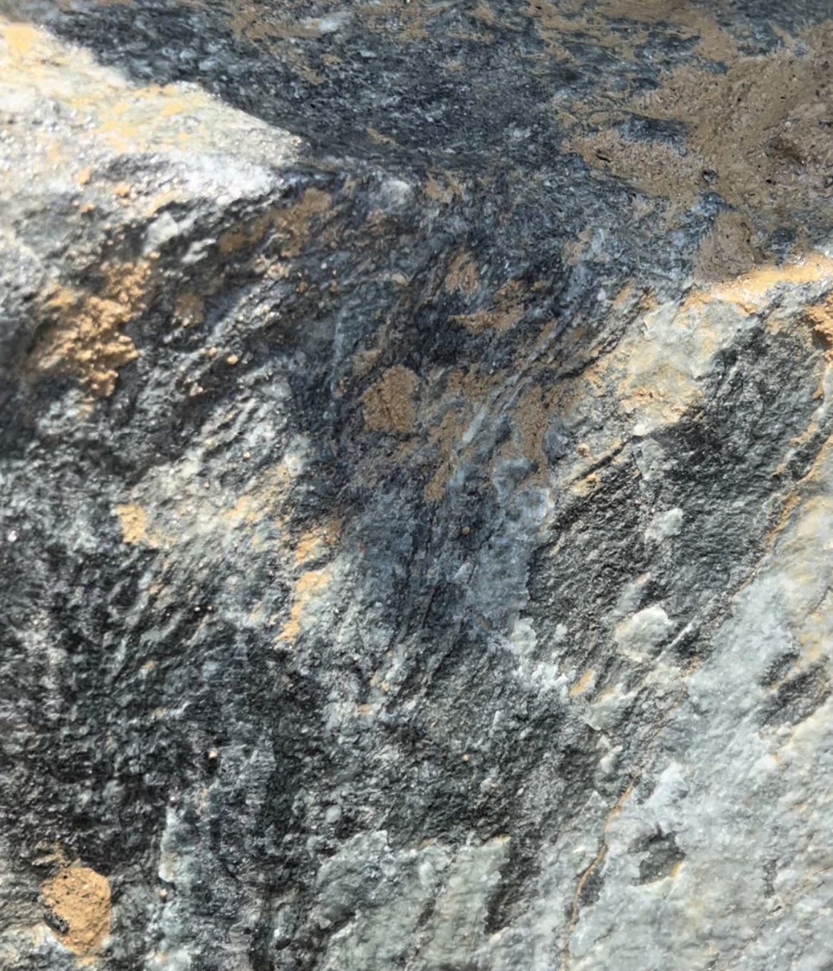
The site notes used different rock descriptions at different visits: monzogranite / granite-amphibolite for the initial samples, then weathered mudstone through moderately and slightly weathered gneiss on 30 June. The 1 July run was described as slightly weathered rock. These field descriptions do not establish one uniform granite interval for the full 50+ m follow-up.
1 July · follow entry through to the final depth
The log records a design pile depth of 26.89 m and rock entry at 21.66 m, where the bullet-tooth barrel could no longer advance. Initial roller-bit entry used 6–7 r/min. Once the face became stable, the recorded head speed was 8–10 r/min.
| Recorded stage | Head speed | P4 channel reading |
|---|---|---|
| Initial rock entry · E1 mode | 6–7 r/min | 4.0–6.0 |
| After the rock face became stable | 8–10 r/min | 5.0–8.0 |
These are the settings observed on that rig and interval, not universal operating limits for a 1,200 mm barrel. The logged window ran from 22.67 m at 12:59 to 27.46 m at 18:24: 4.79 m including intervening work.
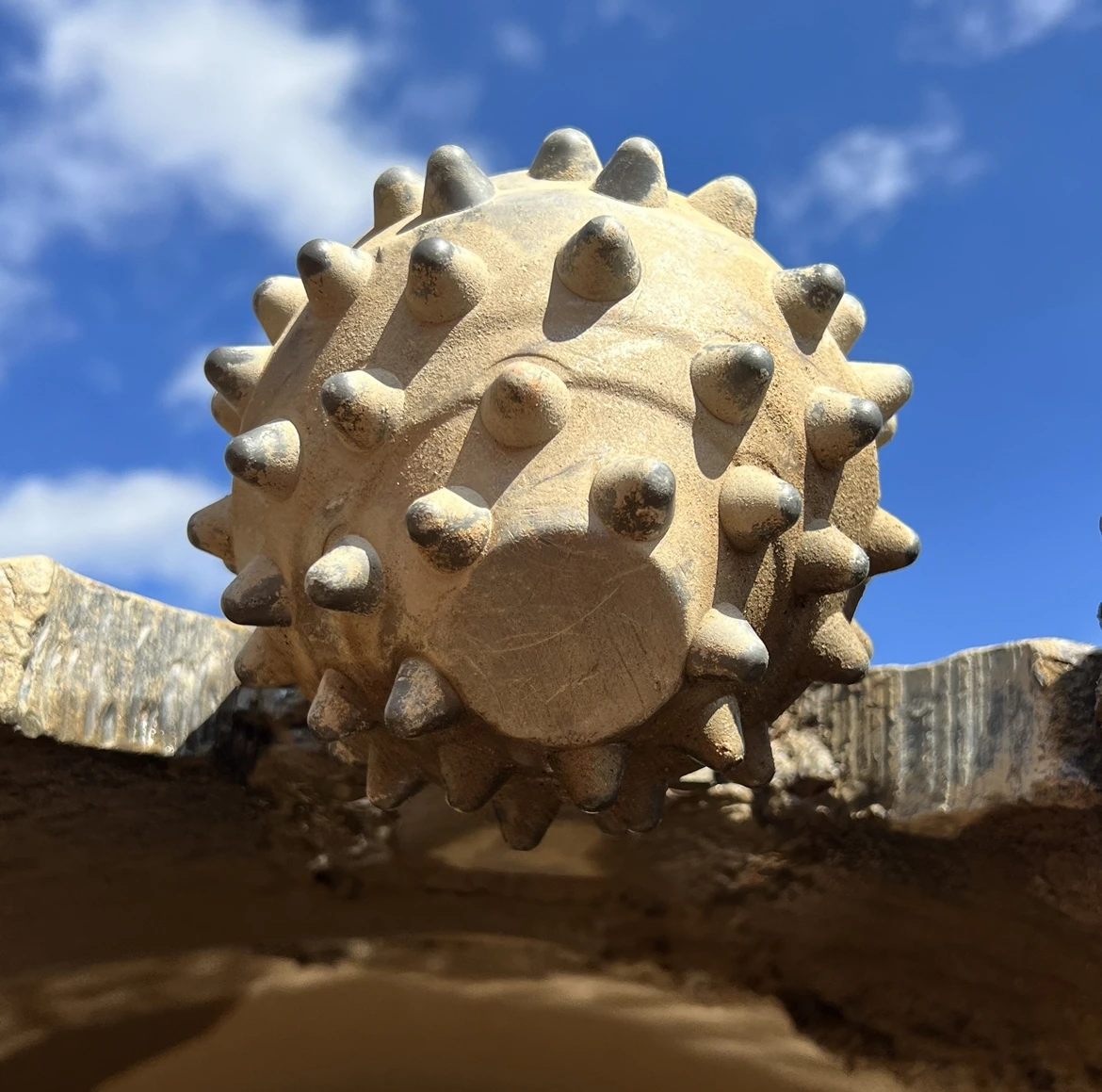
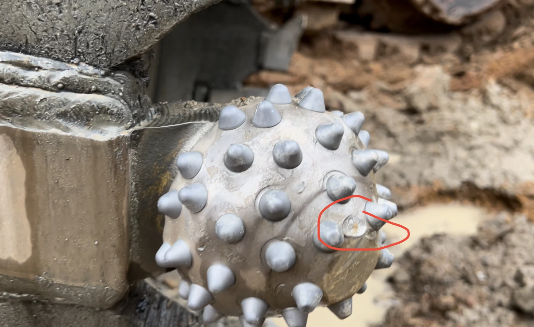
After core recovery, the operator felt strong vibration on re-entry and large loose fragments. Three broken inserts were recorded at the 1 July inspection. The response was to review gentle re-entry, removal of loose fragments, and the relationship between the two barrels’ cutting paths.
Check the companion barrel as part of the same problem
The 1 July measurements were 1,200/110 mm for the bullet-tooth barrel and 1,180/120 mm for the roller-bit barrel: maximum cutting diameter / radial groove width. A groove cut by the first tool might interfere with the back of the following roller cones. This became a design check, rather than treating every broken insert as a cutter-material problem.
Companion-barrel dimensions and calculation notes
| Tool / record date | Maximum cutting diameter | Radial groove width | Core diameter basis |
|---|---|---|---|
| Bullet-tooth barrel · 24 June | ≈1,180 mm | 110 mm | ≈960 mm recorded |
| Bullet-tooth barrel · 1 July | 1,200 mm | 110 mm | 980 mm calculated |
| MH-3 roller barrel · 1 July | 1,180 mm | 120 mm | 940 mm calculated |
Calculated core diameter = maximum cutting diameter − 2 × radial groove width. The earlier 24 June bullet-barrel measurement differs from 1 July and remains in the dated record. The proposed contact mechanism was not independently verified.
The original 1 July narrative estimates 0.7 m/h. Its stated 4.79 m / 325-minute window calculates to 0.88 m/h. The reason for the difference is not recorded, so neither figure is presented as a proven speed improvement or a pure-cutting rate.
August · inspect every position and follow the running record
Follow-up continued after the site installation visits. The 26 August review combined the operator’s running record with a check of all five outer and five inner cutter positions. Its overall assessment was that condition after about 45 m was reasonably acceptable, while three abnormal positions required attention.
Two bearings were seized. Outer position 2 also had a cracked weld; outer position 3 had more extensive insert breakage. Replacement of the three abnormal roller bits and repair of the cracked weld were recommended. The favourable overall assessment did not mean these faults could be left in service.
View the photographs and notes for all ten positions →
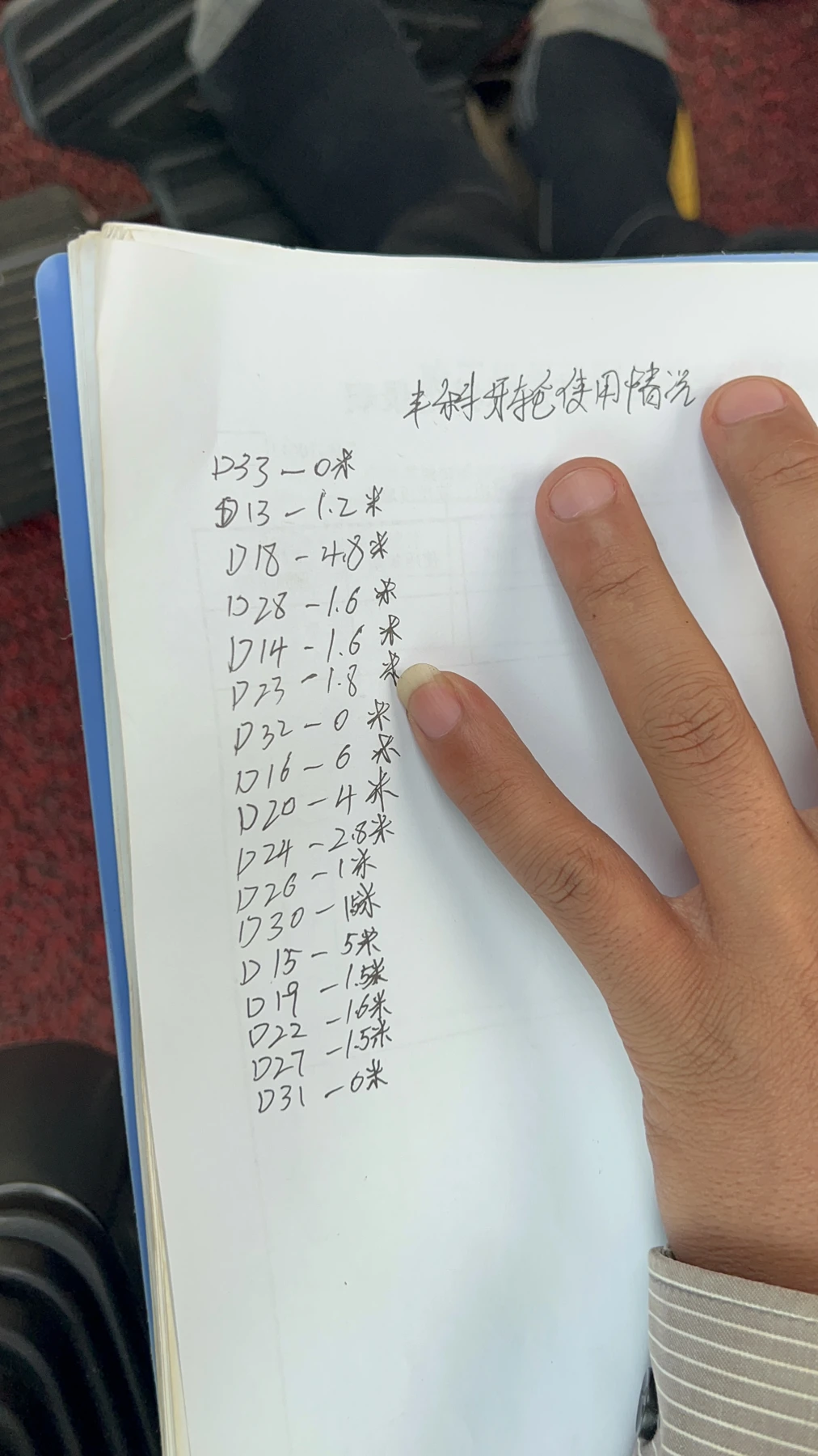
The refitted assembly’s cumulative record reached about 51 m on 30 August and 57 m on 31 August. This follow-up showed how the customer continued using the existing barrel after the MH-3 refit. The same updates identified a heavily worn cutter and further insert breakage, which fed into the repair and design recommendations below.
Operator’s handwritten record and dated mileage history
| Date / stage | Recorded work or running total | Condition / interpretation |
|---|---|---|
| 30 June | ≈1.2 m at the early inspection | Carbide and legs in good condition; light cone/back wear |
| 1 July | 22.67 → 27.46 m between 12:59 and 18:24: 4.79 m in the logged window | 3 broken inserts recorded; loose core fragments and paired-tool geometry considered |
| 26 August | ≈45.9 m: 35.9 m from earlier records + ≈4 m estimated across 4 missing pile entries + 6 m on 24–25 August | 2 seized bearings and an outer weld crack; replacement of 3 abnormal roller bits proposed |
| 30 August | ≈51 m running total; approximately 5 m added in the latest entry | One roller bit recorded as heavily worn |
| 31 August | ≈57 m running total | Severe outer insert breakage and further inner insert breakage recorded |
About 45.9 m comprises 35.9 m from the earlier record, about 4 m estimated for four missing entries, and 6 m from 24–25 August. Later totals are approximate. Replacement history between these entries is not confirmed; 57 m is the last reported cumulative work, not a certified life for one unchanged set.
What did the customer gain from this work?
The customer put an existing barrel back into rock drilling with MH-3 roller bits, on-site installation support and a practical operating handover. The final update recorded approximately 57 m of cumulative drilling. The team’s assessment was that penetration was satisfactory for the conditions encountered; the 1 July log recorded 4.79 m over its timed operating window, including intervening work.
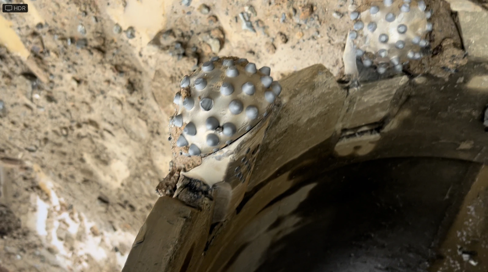
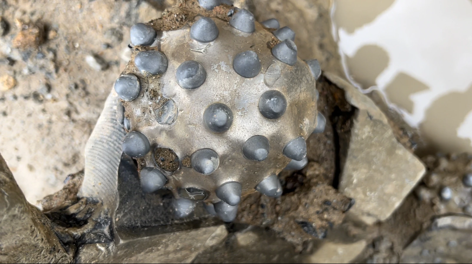
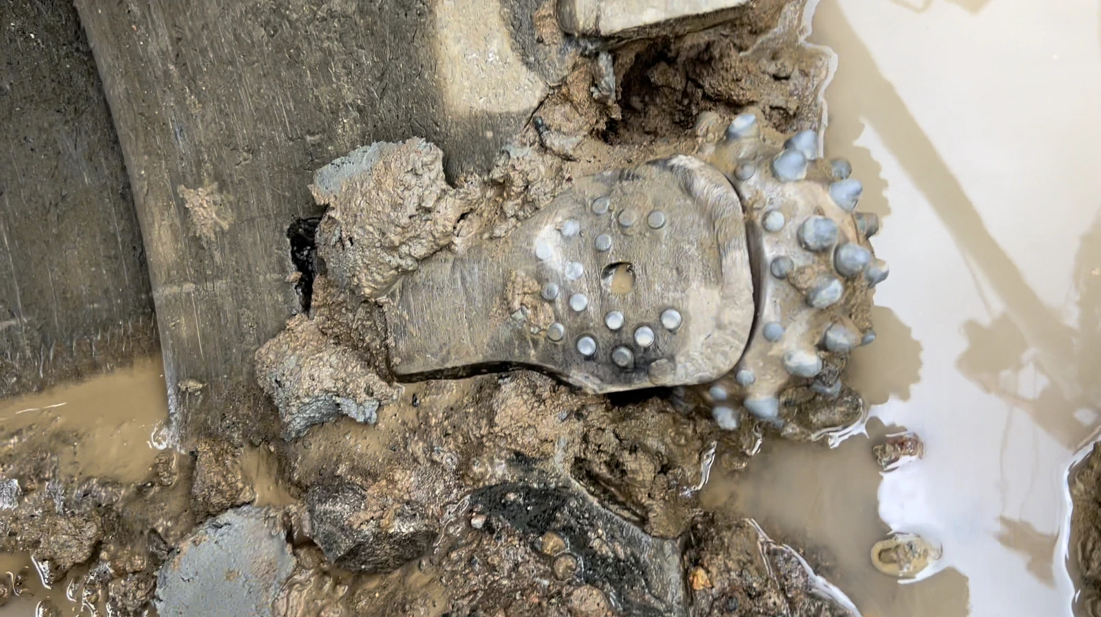
Roller-bit condition after about 45.9 m
Two selected views from the last complete ten-position inspection. The notes described overall wear at these positions as acceptable; the full record below includes the positions that needed repair or replacement.

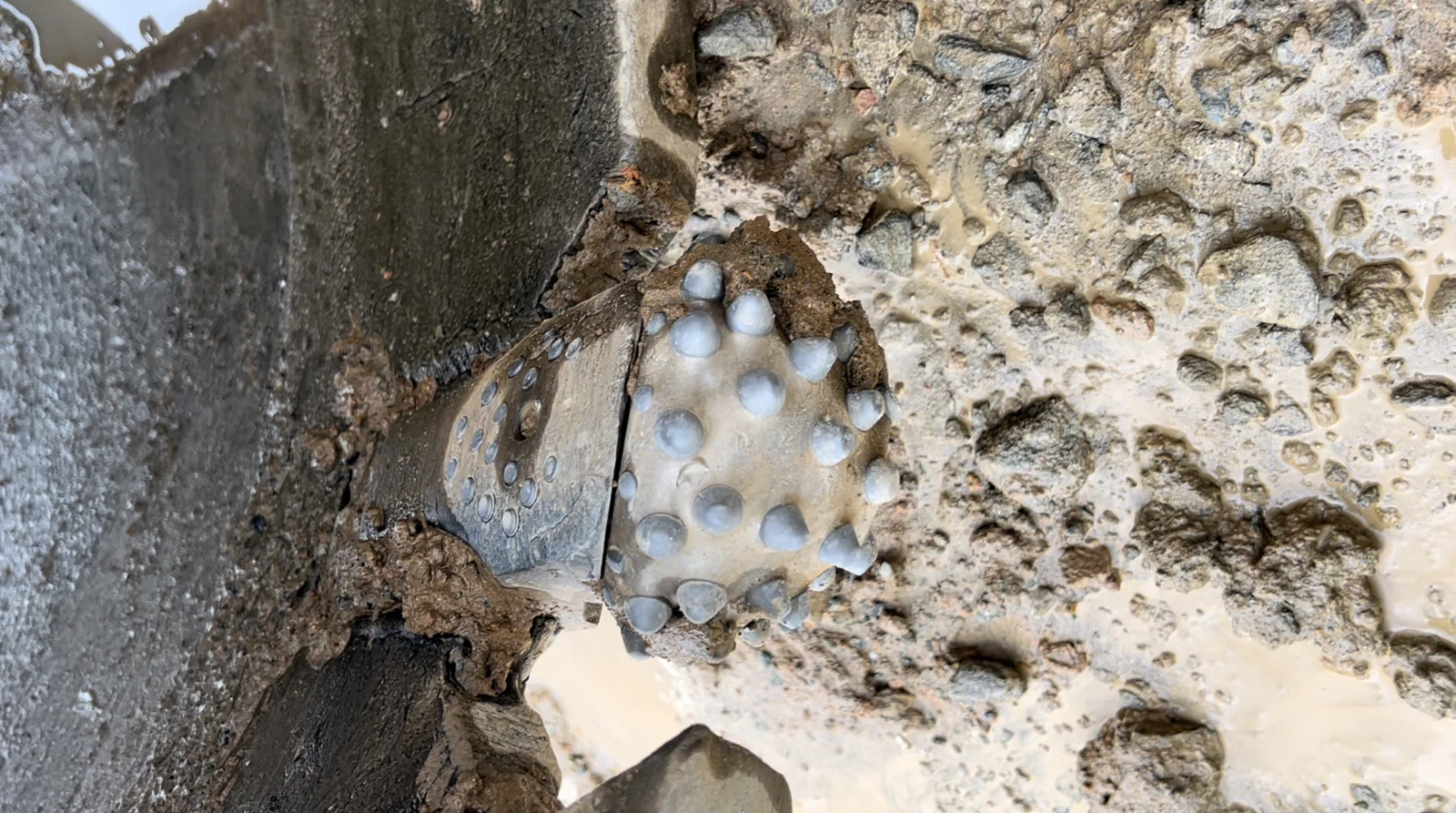
View all ten positions · 26 August
Last complete position inspection · approximately 45.9 m. One photograph for each of the five outer and five inner positions, paired in the order used in the original inspection. These views precede the approximately 57 m update on 31 August.
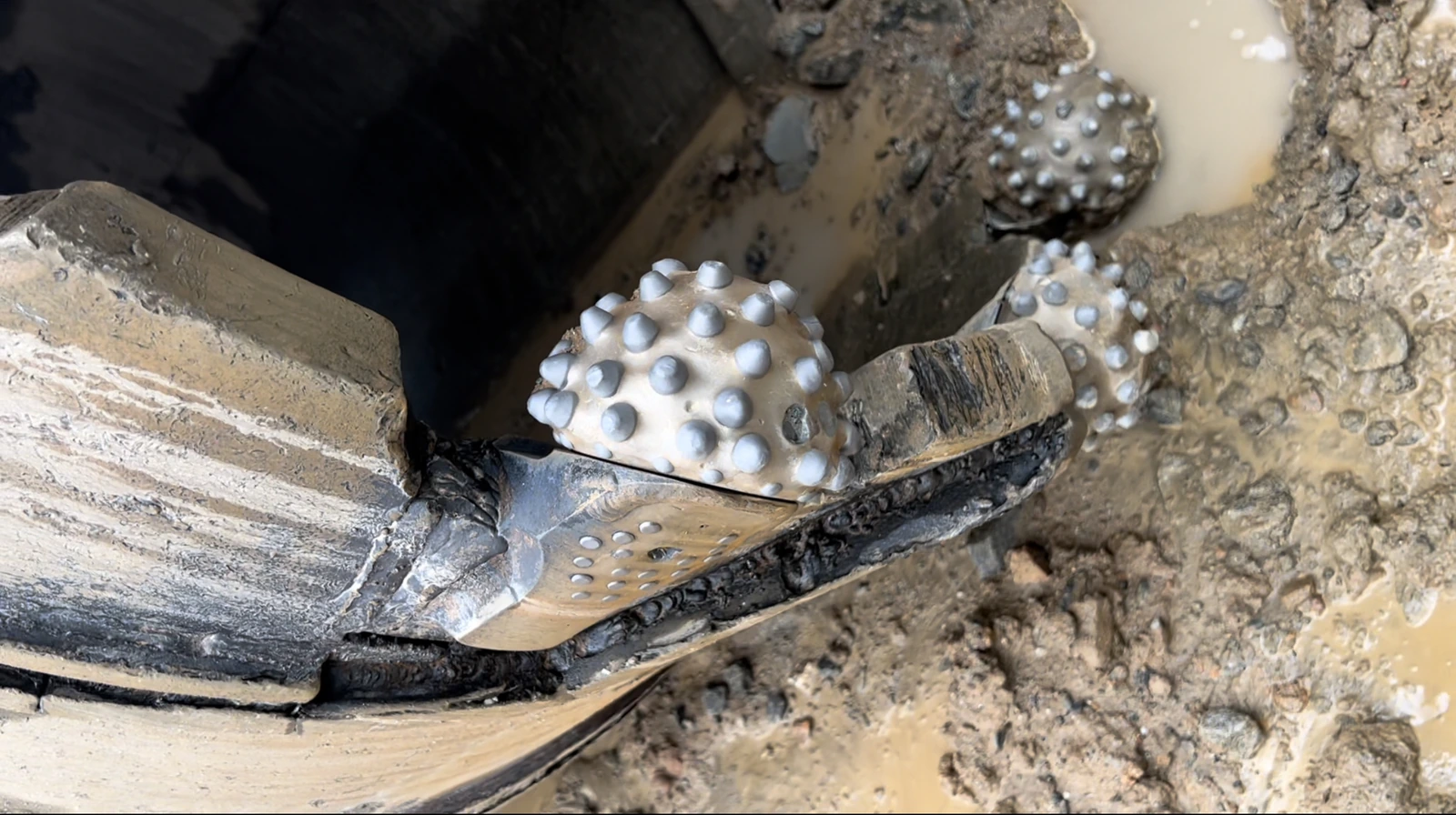
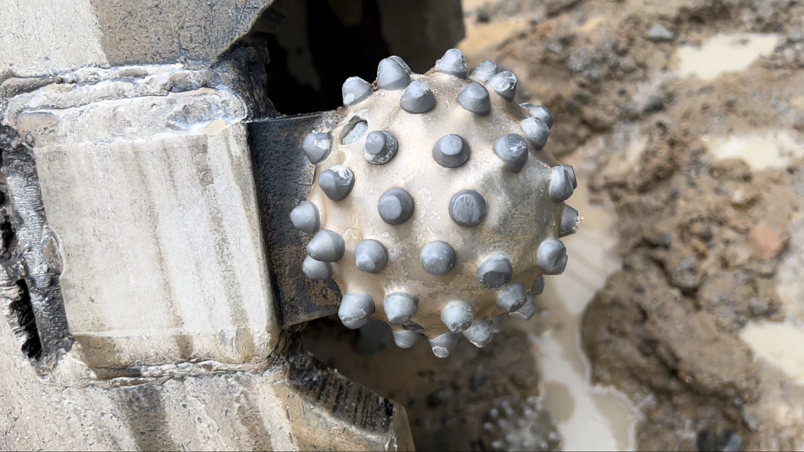
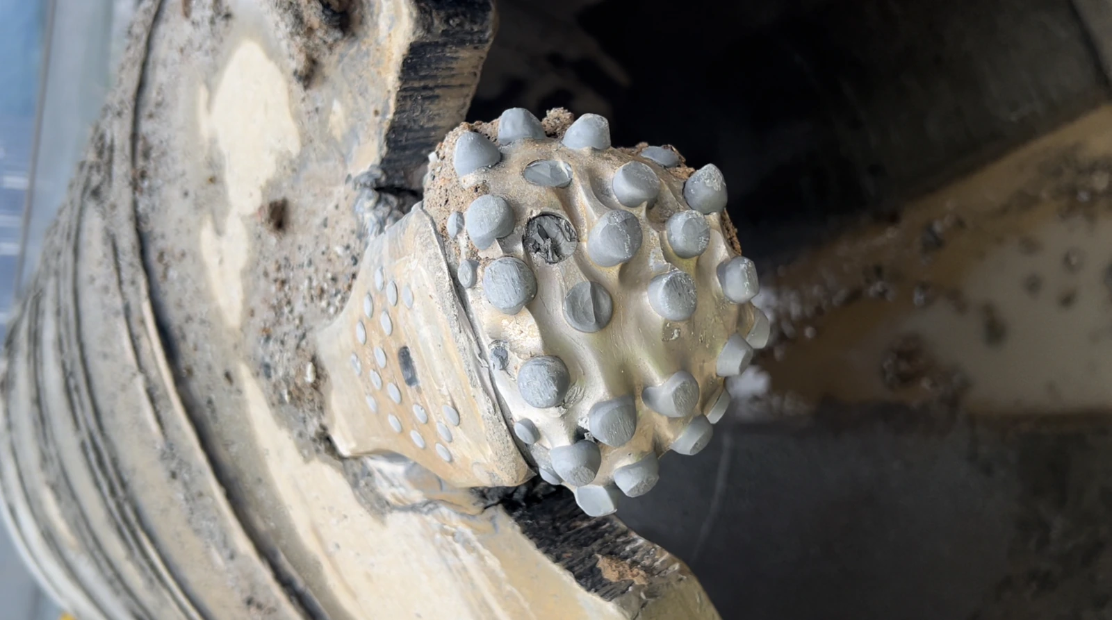
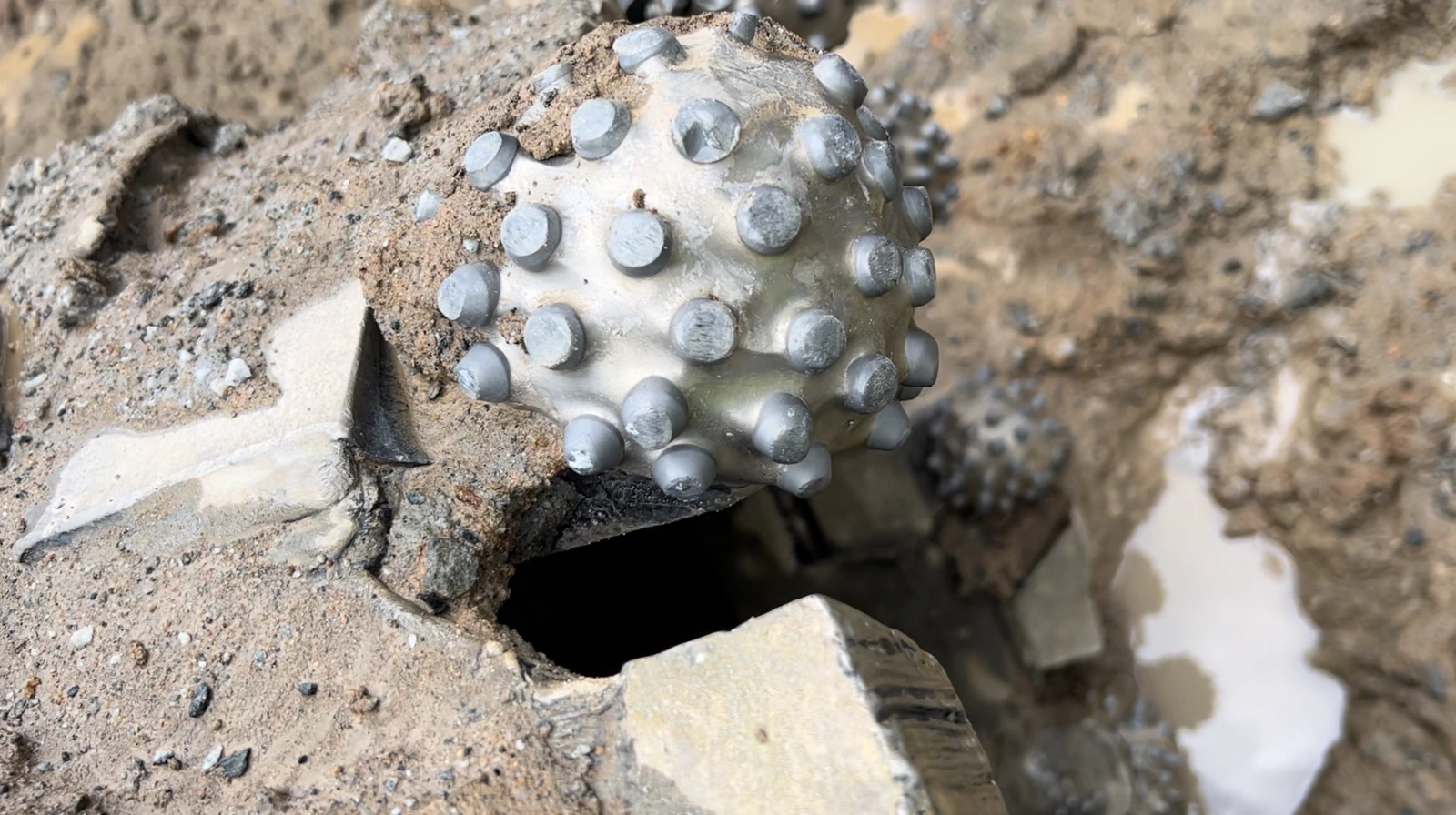
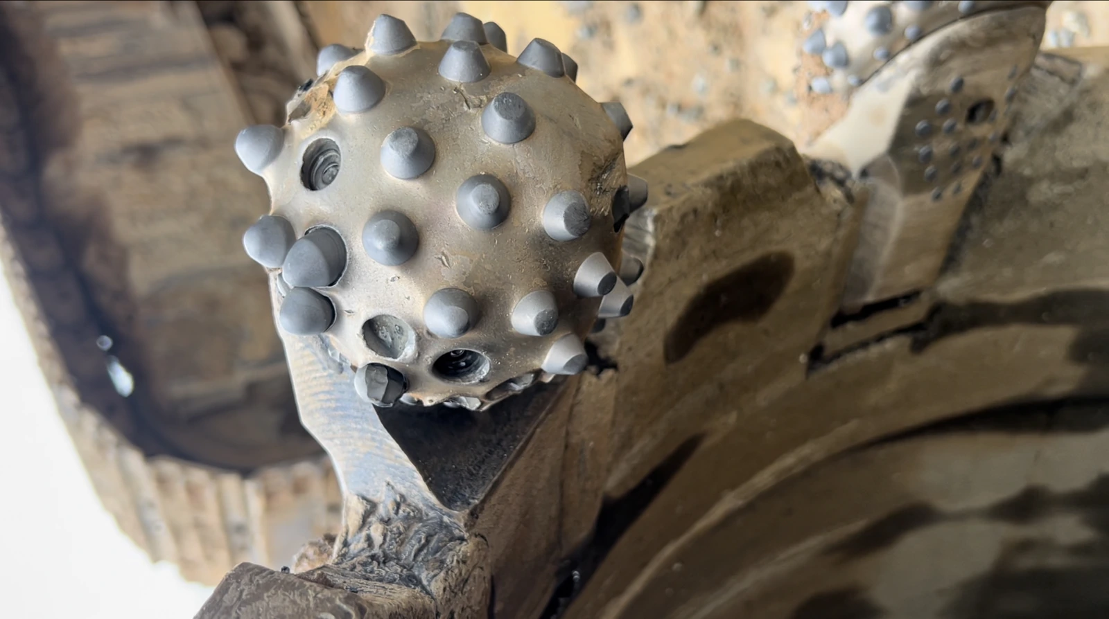
| Position | Condition in the source inspection |
|---|---|
| Outer 1 | Some broken inserts; bearing reported normal |
| Inner 1 | Some broken inserts; bearing reported normal |
| Outer 2 | Bearing seized, substantial tooth wear; weld crack recorded |
| Inner 2 | Tooth wear described as acceptable; bearing seized |
| Outer 3 | More extensive insert breakage |
| Inner 3 | Overall wear described as acceptable |
| Outer 4 | A few broken inserts |
| Inner 4 | Overall wear described as acceptable |
| Outer 5 | Overall wear described as acceptable |
| Inner 5 | Overall wear described as acceptable |
The review identified Outer 2, Inner 2 and Outer 3 for replacement, with a weld repair also required at Outer 2. Positions are the original inspection labels, not permanent serial numbers. The record does not confirm when these replacements were completed.
A working refit, backed by hands-on support
The scope covered the customer’s problem tool, its measurements and layout, assistance to the site welder, and checks of cutter positioning before full welding. The customer’s crew gained direct experience of the fitting references and control points. Guide-strip finishing remained a separate issue in the end-of-day photographs.
Operators who understood the operating approach
Training and handover connected the tool to its use: establish stable contact, adjust speed and loading to the drilling response, keep cuttings moving, and inspect after lifting. The incoming operator was included in the handover.
Follow-up that produced the next improvement decisions
At around 45 m, the field review described overall condition as reasonably acceptable and identified individual roller bits and a weld that needed attention. Continued reports through approximately 57 m led to proposals for better guide-strip clearance, companion-barrel geometry and cutter protection. This gave the customer specific actions to discuss for the next repair and drilling run.
For a contractor with a problem barrel, this case shows the support we can discuss: survey the existing assembly, define the refit, guide installation and operators, then follow the drilling and wear records.
Remaining issues and next design proposals
| Finding | Next proposal in the original record |
|---|---|
| Site fitting consumed time and scraper cuts varied | Consider a preassembled lower ring with roller bits and scrapers; pre-cut bevels and confirm the retained shell dimensions |
| Dry, packed cuttings and steel wear around the cone | Review taller/wider guides, top-plate clearing features and fluid/clearing practice |
| Cone-back wear and re-entry impact | Review protective inserts on the cone back, companion cutting paths and re-entry after core recovery |
| Insert breakage was more prominent than uniform carbide wear | Consider an MH-1 trial with fewer inserts to test cost per metre; this was a proposal, not an adopted or validated replacement |
| Operating practice affected the complete result | Develop a practical operator guide and troubleshooting reference from the site observations |
| Evidence from the visit | Work status | Next design question |
|---|---|---|
| 10 MH-3 positions set, 4 scrapers added, spirals partly repaired | Completed site refit | Review the proposed supply of a cutting ring assembled with roller bits and scrapers for a later rebuild. |
| About 10 mm variation noted in scraper bevel cutting | Observed during site work | Pre-cut bevels and agree the scraper geometry before installation |
| Packed, relatively dry cuttings and cone-back wear | Observed during use | Review guide height, fluid/clearing practice and the companion barrel’s cutting path |
| Bearing seizure, insert breakage and weld cracking at later inspections | Observed; replacement/repair proposed | Keep individual cutter IDs and record the work completed before the next mileage segment |
For a new trial, record the rig and ground interval, cutter positions, each replacement, drilling and recovery time, and the next inspection decision. That connects measured output and wear to the actual configuration in use.