

 WS39 casing tooth
 JM cutter tooth
 B47K22 bullet tooth
A jumping or vibrating roller-bit core barrel needs a whole-tool check. Start with when it begins, then review the cutting geometry and operating conditions before changing the settings.
When does the jumping begin?
For abnormal jumping or unstable rotation, stop and follow the rig and site procedure. Inspect the recovered tool only when supported and isolated. Do not increase drill pressure simply to force an unstable assembly to keep cutting.
| When it starts | Check first | Keep with the record |
|---|---|---|
| As the cutters engage the rock | Review engagement, the complete cutting geometry, cone condition and the operating readings with the rig team. | Whether it occurs only on contact or continues in the cut; depth, ground observations and the readings at that time. Identify what each displayed pressure represents. |
| After welding, rebuilding or changing cutters | Re-establish the centre reference. Compare radial position, cutter projection, sideways orientation, guides and scraper from the same datum. | The as-built drawing, measured differences and which components changed. A copied first position can carry an error around the ring. |
| At a new depth, layer or enlargement pass | Check the ground transition, debris, cutter condition and cutting envelope. Include the Kelly/tool connections in the inspection. | The onset depth, last stable interval, preceding tool and whether this is bottom-hole cutting or enlarging an existing hole. |
Timing narrows the questions; it does not prove the cause. If several geometry or operating items change together, retain the baseline and assess the combined change in a comparable interval.
Photographed field inspection
In this inspection, spoil-guide height was reported at about 60 mm against a 50 mm design value, and the scraper was described as level with the roller bits without the intended inclined cut. These are separate findings for this tool. The 50 mm value is not a universal guide-height specification.
How do the guide strips project relative to the cutters?
Inspect the full circumference and measure guide projection against the selected drawing reference. Record each measurement position and photograph the guide and neighbouring roller bits together.
The visit identified guide height above the design value for review alongside scraper geometry, cutter positions and operating conditions.
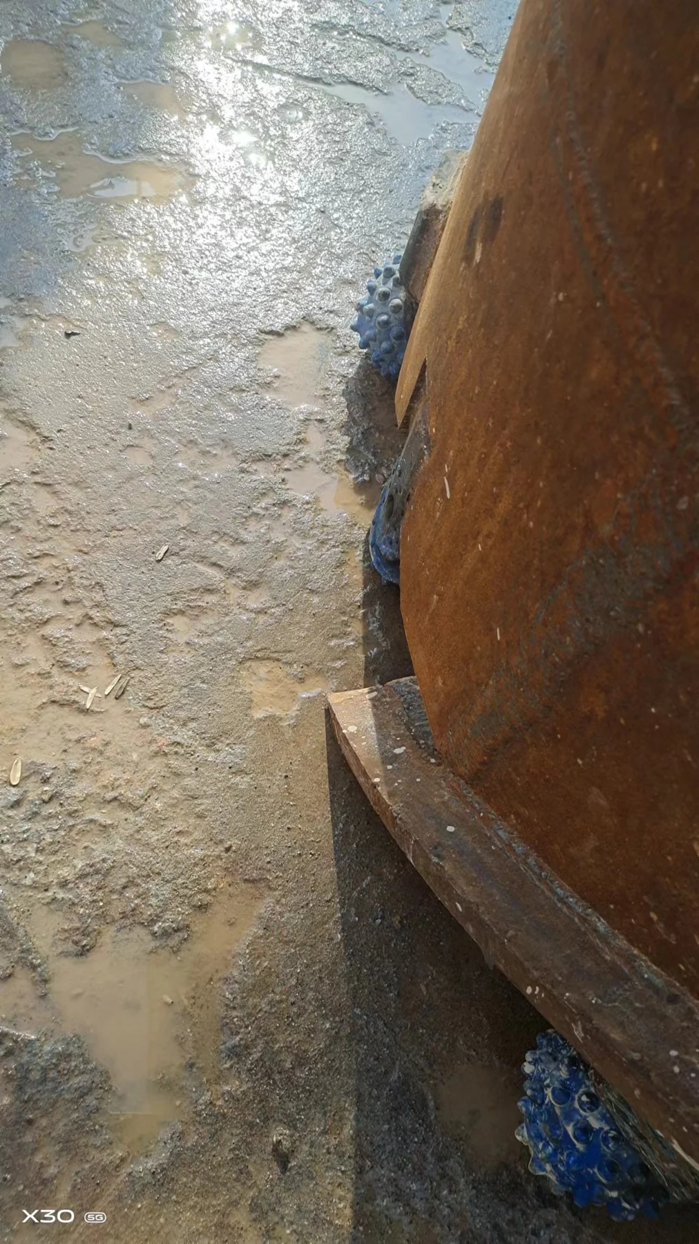
Are the scraper and guide edges consistent with the layout?
Check scraper position, cutting-edge shape, guide ends and neighbouring cutter placement as one arrangement. The record described a scraper edge level with the roller bits and without the inclined cutting form under discussion.
Record proposed changes and the welding adjustments mentioned in the review. Keep the before and after geometry separate, using the same reference points for both.
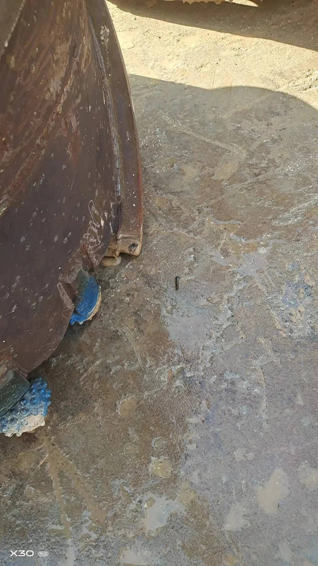
Record the event and the complete tool
- When it starts. On contact, during cutting, after a tool change or at a different depth. Note whether it stops when the cutting condition changes.
- The layout and measurements. Full cutting-end view, numbered cutter positions and close-ups of guides, scraper, mounts and contact marks. Keep before/after-welding measurements separate.
- The operating context. Rig and barrel identification, depth and ground information, rotary-head rpm, the name and unit of each pressure reading, and recent tool or setting changes. Include any existing footage recorded from a safe position; do not recreate the event for a video.
Use the operating-readout guide to distinguish pressure, torque and speed. If the same event also reduces progress, keep cutting and interruption times separate.