

 WS39 casing tooth
 JM cutter tooth
 B47K22 bullet tooth
Check the outer and inner working points of the roller bits from a common centre, then check projection and orientation from a defined plane. Pile diameter and steel-ring diameter alone cannot locate the complete cutting envelope.
Are radius and projection being measured separately?
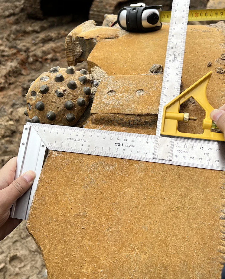
Measure the existing ring before copying a layout: distortion or worn openings can move the reference surfaces. Record the centre, reference plane, opening depth and intended cutter position on the selected drawing.
Equal radius does not establish equal cutter height. Check equivalent points within each row; inner and outer rows may have different intended geometry. Use top, side and across-leg views to separate radial position, projection and sideways tilt.
Which circle defines the cutting path?
The outer cutting path, steel-ring reference and inner cutting path serve different purposes. The radial groove width is half the difference between the two cutting diameters; it is not the clearance measured from the steel ring.
Check the first inner and outer roller-bit positions, then remeasure the complete tack-positioned arrangement. Recheck after welding using the agreed procedure, including heat controls for the assembled roller bits.
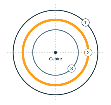
Calculate the groove before setting the cutter positions
In the January 2024 layout, the outer path was 1,770 mm, the steel-ring reference was 1,650 mm and the inner path was 1,530 mm. Convert the diameters to radii before using a centre fixture.
| Reference | Diameter | Radius from the common centre |
|---|---|---|
| Outer working path | 1,770 mm | 885 mm |
| Steel-ring reference | 1,650 mm | 825 mm |
| Inner working path | 1,530 mm | 765 mm |
Radial groove: (1,770 − 1,530) ÷ 2 = 120 mm.
Reference offsets: 885 − 825 = 60 mm; 825 − 765 = 60 mm.
The two 60 mm differences are geometric offsets between reference circles. They do not describe free mechanical clearance around a leg, holder or weld. Measure projection from the specified plane as a separate coordinate.
- Mark the outer and inner working points on the first pair and verify their radii against the layout.
- Measure the equivalent working points in each row; a measurement on the steel leg cannot substitute for a measurement on the specified cutter point.
- Inspect all tack-positioned cutters before final welding. If one sticks outside its intended path, resolve its position before using an average of the other readings.
ENGINEERING REVIEW · 2,000 mm PILES
From five working diameters to a three-stage proposal
A recent project enquiry started with five core-barrel diameters for a 2,000 mm final pile. Our review asked a more useful question: which sequence gives the cutters a workable engagement path while keeping core breaking, recovery and tool changes manageable?
Design-stage example. The comparison below describes a proposed method. Site trials and final engineering checks are still required; it is not a completed drilling-performance result.
| Review point | Initial request | Proposed sequence |
|---|---|---|
| Working diameters | 1,000 → 1,200 → 1,500 → 1,800 → 2,000 mm | 1,200 → 1,600 → 2,000 mm |
| Enlargement steps | Four after the first core hole | Two after the first core hole |
| What must work | Small radial steps must be checked against the cutter width and the previous opening. | Larger steps need effective guidance and a planned way to break and recover the remaining rock. |
| Trade-off | More diameter options to manage and maintain | Fewer diameters, but more rock to remove at each enlargement |
Why the cutting band changes the comparison
For the proposed 1,200-to-1,600 mm step, the nominal radial increase is 200 mm. With the 120 mm radial cutting band assumed in this design study, the ideal concentric geometry leaves an 80 mm residual rock rib:
(1,600 − 1,200) ÷ 2 − 120 = 80 mm
The same calculation applies to the 1,600-to-2,000 mm step.
This is a geometry calculation, not a guaranteed support margin or an acceptable offset limit. Actual cutter projection, guide clearance, hole shape and wear change the relationship. A remaining rib also needs a defined breaking and recovery operation.
Cut, recover, then enlarge
- Establish the first core hole. Plan controlled cutting lifts together with core breaking and recovery.
- Guide each enlargement from the preceding opening. Check the actual opening and guide fit before committing to the next stage.
- Prove the complete cycle. Compare cutting, core breaking, lifting, clearing and tool-change time, alongside wear and final hole geometry.
The three-stage proposal reduces the number of planned enlargement steps. It does not reduce the total rock volume or prove a saving in time or cost. Final tool mass, rig and Kelly limits, guide design, cutter layout and representative trial results remain part of the decision.