

 WS39 casing tooth
 JM cutter tooth
 B47K22 bullet tooth
Inside the workshop
Manufacturing & QC.
See the work behind roller bits, cutting teeth and core-barrel assemblies: component machining, carbide-insert brazing, dimensional checks and cutter positioning.
Explore roller-bit manufacturing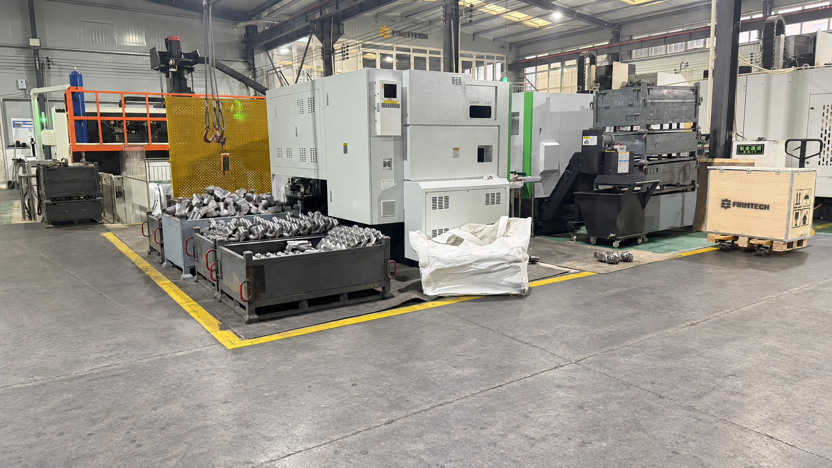
Components & tool assemblies
From individual parts
to the complete tool.
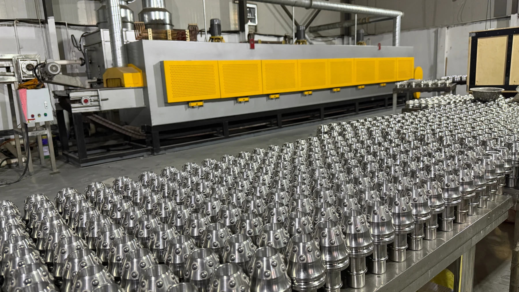
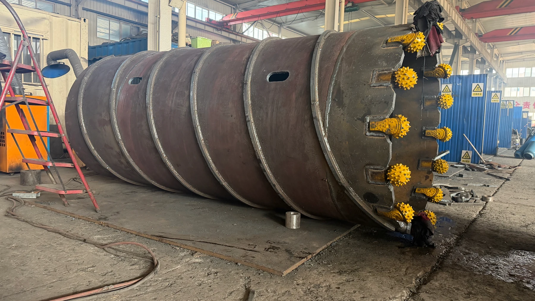
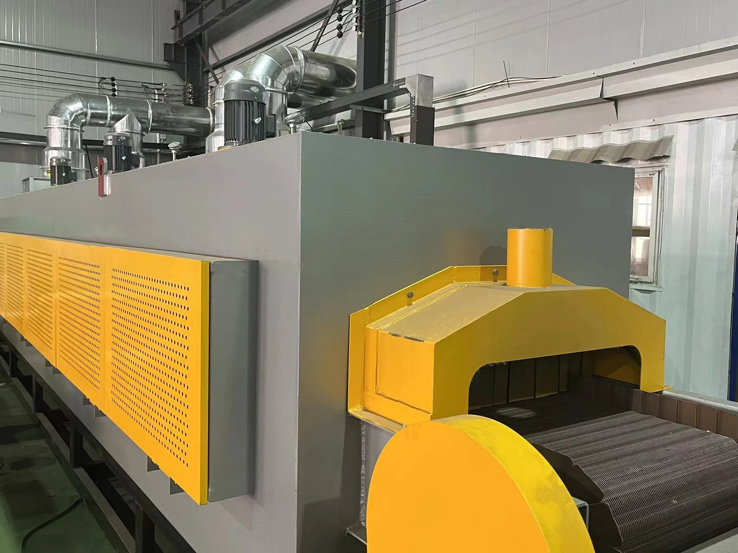
Cutting-tooth bodies in batches. A roller-bit core barrel on the workshop floor. Follow the product-specific manufacturing stages and checks below.
ROLLER BITS
From the journal to the assembled fit.
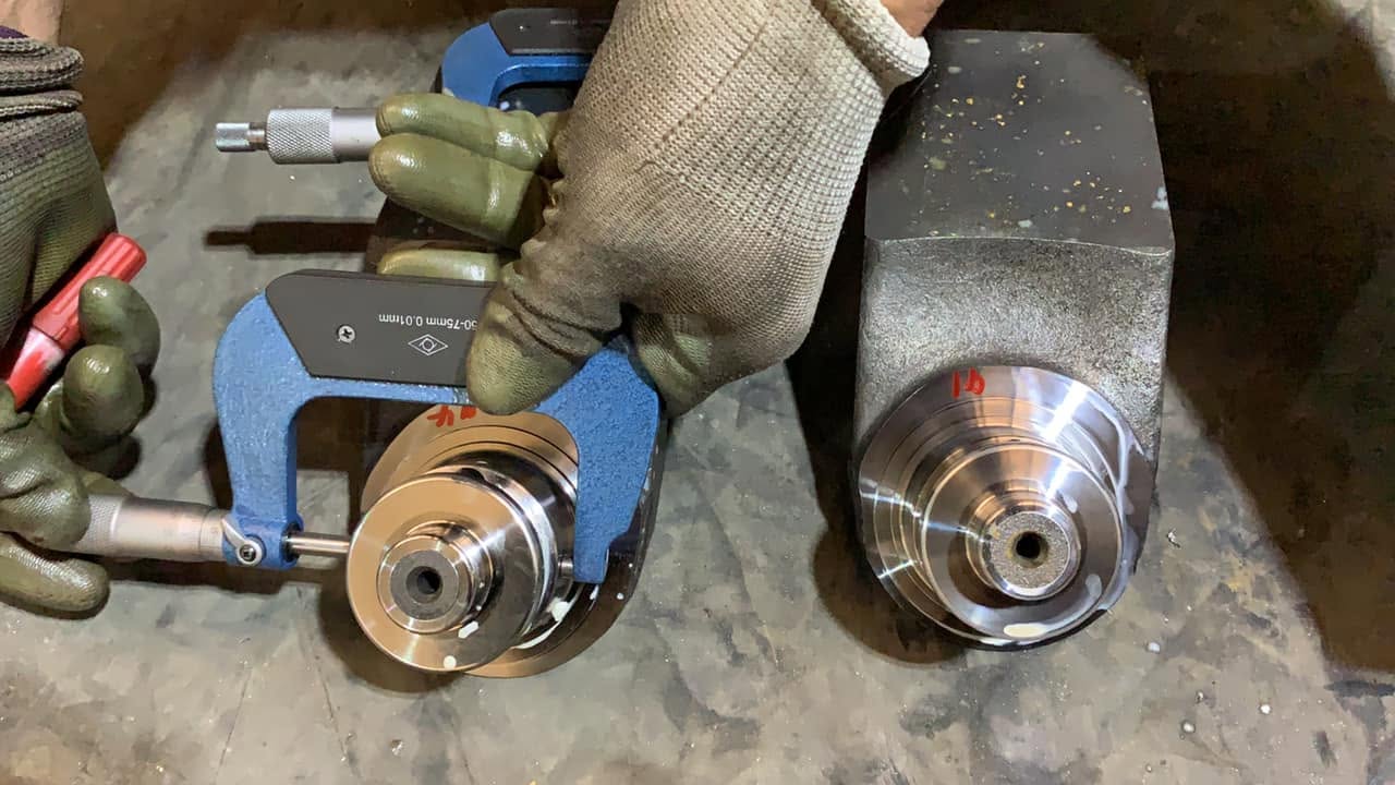
The MH-3 process record follows grooving, hardfacing, heat treatment and finish machining. Measurement then connects the finished journal to the mating cone, seal region and assembled fit.
Manufacturing record
See the actual component at six stages, from prepared grooves to finished bearing surfaces.
Follow the process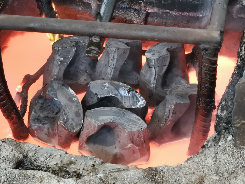
Dimensions and fit
Journal diameters, matching cone bores, seal geometry and assembled movement are separate inspection points.
View the roller-bit inspection recordCutting teeth / Production & inspection
The carbide joint.
The steel body.
Brazing joins the carbide insert to the body. Heat treatment and hardness checks address the body condition. Each stage has a different feature to inspect for the selected tooth.
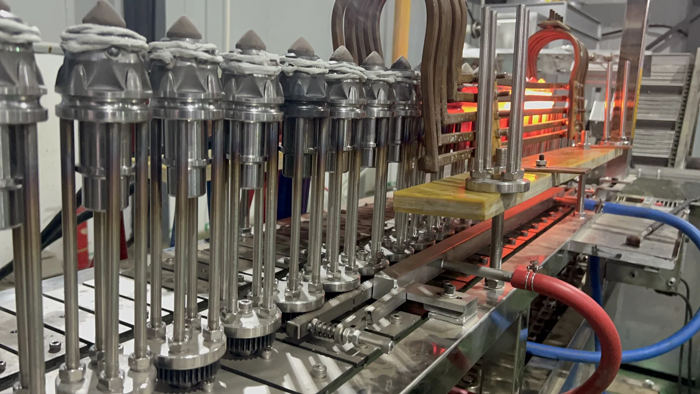
Join carbide to steel
The production photograph shows the insert joint during brazing. Seating, joint support and tooth-body geometry are the inspection focus.
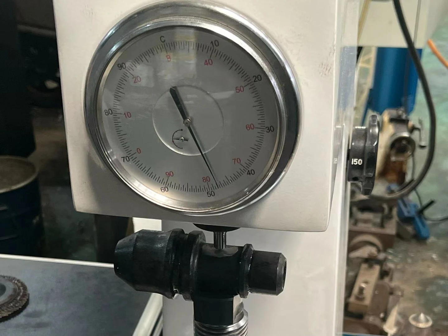
Check the body condition
The indenter contacts the component itself. A useful hardness record identifies the body, process stage, test location and reading.
View bullet teeth and matched holders · Heat treatment & testing photographs
Heat treatment and material-testing records
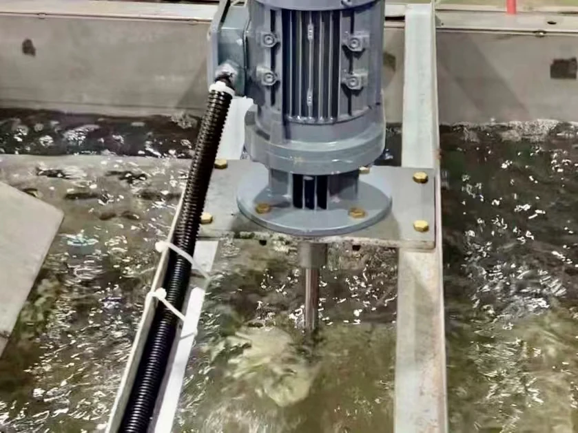
Quenching and tempering are included in the documented tooth-production workflow. Hardness checks and prepared test specimens address different aspects of the body condition.
- Quenching equipmentView the equipment photograph from the production record.
- Tempering equipmentView the furnace and its loading arrangement.
- Sectioning and test specimensSee the cut tooth body and prepared samples used in the material-testing workflow.
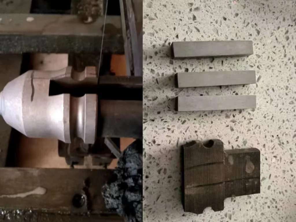
Process settings and acceptance criteria are agreed for the selected product and order.
Assembly record · January 2024
Position the complete
cutting ring.
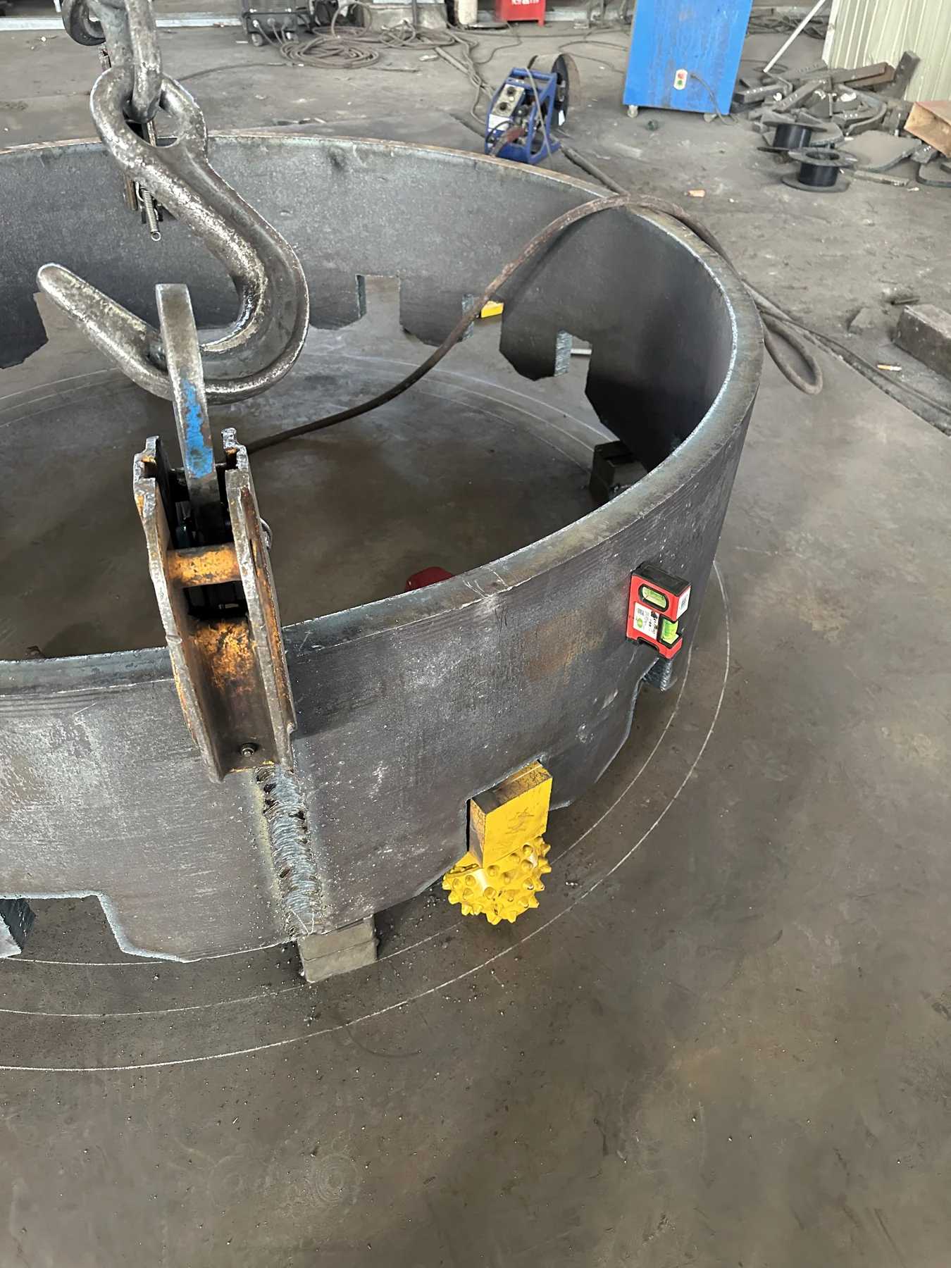
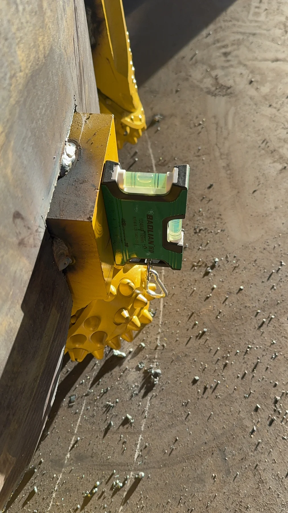
The documented 1,800 mm build brought sixteen roller bits into a common layout. Three concentric references, leg-position checks and remeasurement connected the individual cutters into one cutting ring.
- Set the outer cutting path, steel-ring reference and inner cutting path from a common centre.
- Check leg orientation, sideways twist and lateral displacement with positioning blocks and a level.
- Remeasure the full set and correct individual positions before final assembly.
Inspection & traceability
Keep the checks
with the part.
The photographs show the work. These guides identify the dimensions, material identity and assembly checks to record for the supplied part.
- Roller-bit inspection & traceabilityMaterial identity, bearing fits and inspection results.
- Core-barrel checks before repairCutting ring, old openings and spoil guides.
- Bullet teeth, holders & retainersMatch the tooth reference, mounting dimensions and retaining parts.
- JM cutter-tooth sample inspectionHistorical sample dimensions, carbide position and brazed-joint checks.
Manufacturing & order review
Specify the part.
Agree the checks.
Send the model or drawing, the quantity and the inspection documents your project requires. We can define the dimensions, material records and assembly checks to include with the order.