

 WS39 casing tooth
 JM cutter tooth
 B47K22 bullet tooth
DRILLNOVA / ROTARY DRILLING TOOLS
MH-3 roller bit
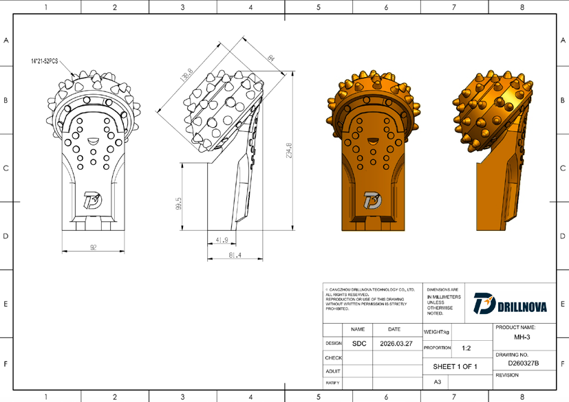
A 52-insert cone. A thicker piling leg with its welding angle built in. Explore the cutting arrangement, bearing protection and installed geometry that define MH-3.
- 52 / Ø14 mm
- Insert count / diameter
- 139 mm
- Catalogue cone size
- Weld-on
- Mounting method

Cutting coverage, bearing protection
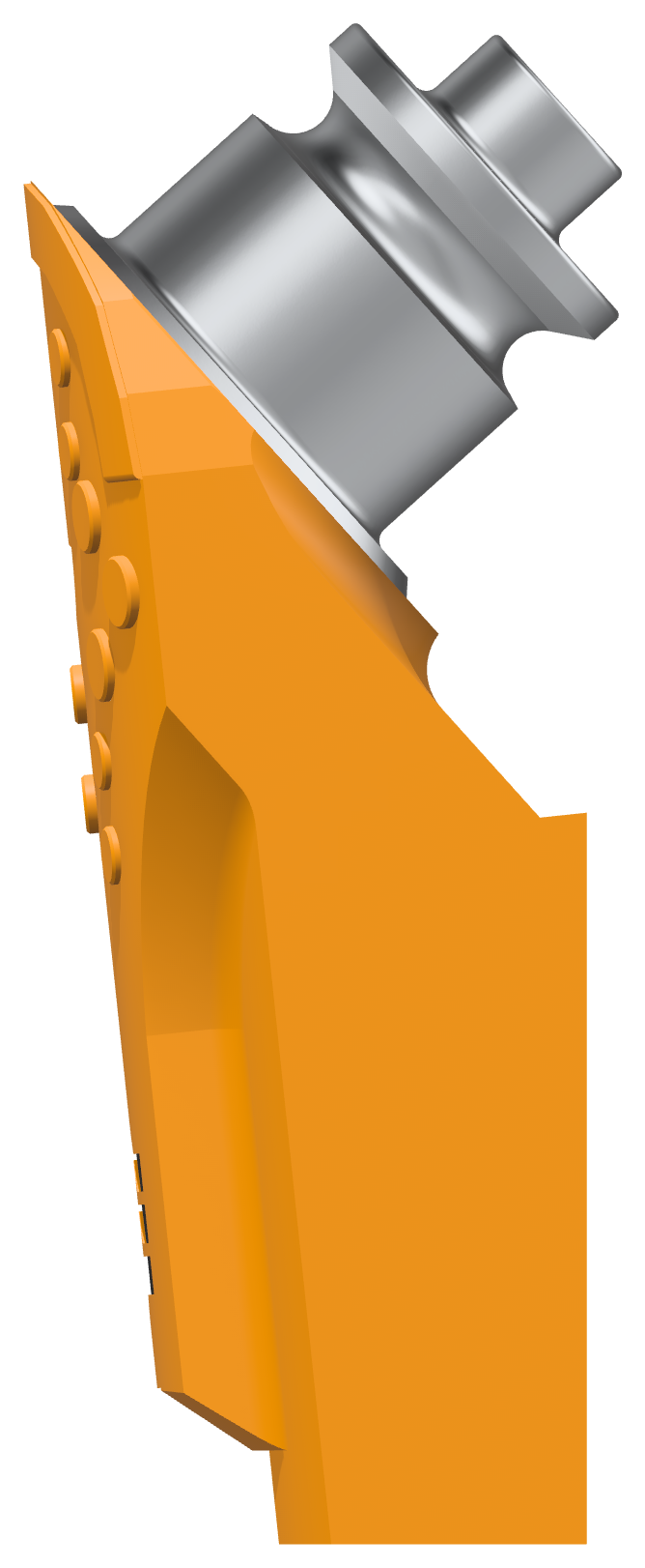
The cone layout extends the insert coverage across spaces left between the earlier rows. The catalogue lists a 139 mm cone size and 14 mm inserts. The outer cutting arrangement also helps shield the vulnerable leg tip: the working inserts should engage the rock while the seal region stays behind the intended cutting path.
Inside the assembly, journal-bearing surfaces carry the cone, grease lubricates the contact, and the O-ring seals the joint. The catalogue describes wear-resistant alloy-coated bearing surfaces, an additional protective layer outside the normal O-ring and vacuum grease filling. These features address different parts of the assembly; insert count alone cannot describe bearing protection.
In abrasive ground, worn supporting steel may expose the seal area before the carbide is consumed. Packed cuttings and excessive heat can also contribute to early bearing problems. If a cone becomes difficult to rotate while its inserts remain usable, inspect the leg tip, seal region and installed position as well as the carbide.
MH-3 specifications
| Feature | MH-3 |
|---|---|
| Mounting | Weld-on |
| Cone / insert layout | 139 mm catalogue cone size; 52 inserts × 14 mm diameter |
| Cone / leg material | Confirm cone and leg grades against the selected drawing |
| Cutting material | Tungsten carbide |
| Bearing / seal | Journal bearing / O-ring rubber seal |
| Lubrication | Vacuum grease system |
| Protection options | Gauge and shirttail protection available |
Nominal specifications; the order drawing confirms the supplied configuration, mounting dimensions and protection options.
ROLLER-BIT DEVELOPMENT
The cone and leg behind MH-3
Three cone generations refine the cutting pattern. Four leg generations refine the welding profile and working-angle setup.
Cone · cutting coverage
Follow the change in insert spacing and coverage.
-
Generation01
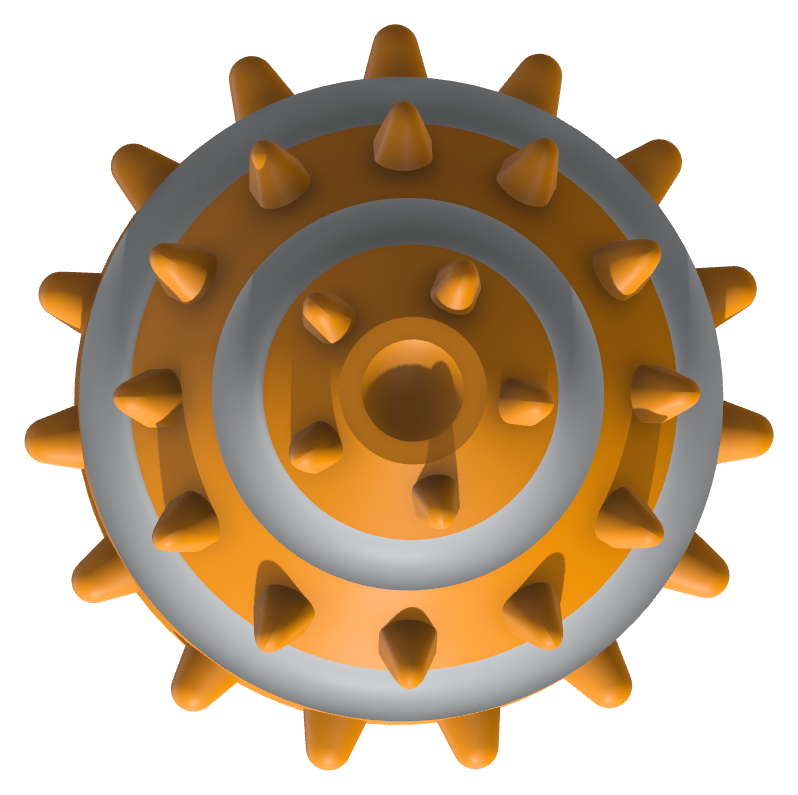
Spaced insert rows
Grooves separate the insert rows, leaving areas between them without cutting points.
-
Generation02

Closer insert coverage
Additional inserts reduce the gaps and extend the cutting pattern across the cone.
-
Generation03MH-3 cone

Extended insert pattern
Cutting points cover more of the cone. The MH-3 configuration uses 52 inserts, each 14 mm in diameter.
Leg · welding profile
From the early irregular profile to the preset-angle piling leg.
-
Generation01

Irregular profile
The tricone-style leg retains its nozzle section and an irregular welding profile.
-
Generation02
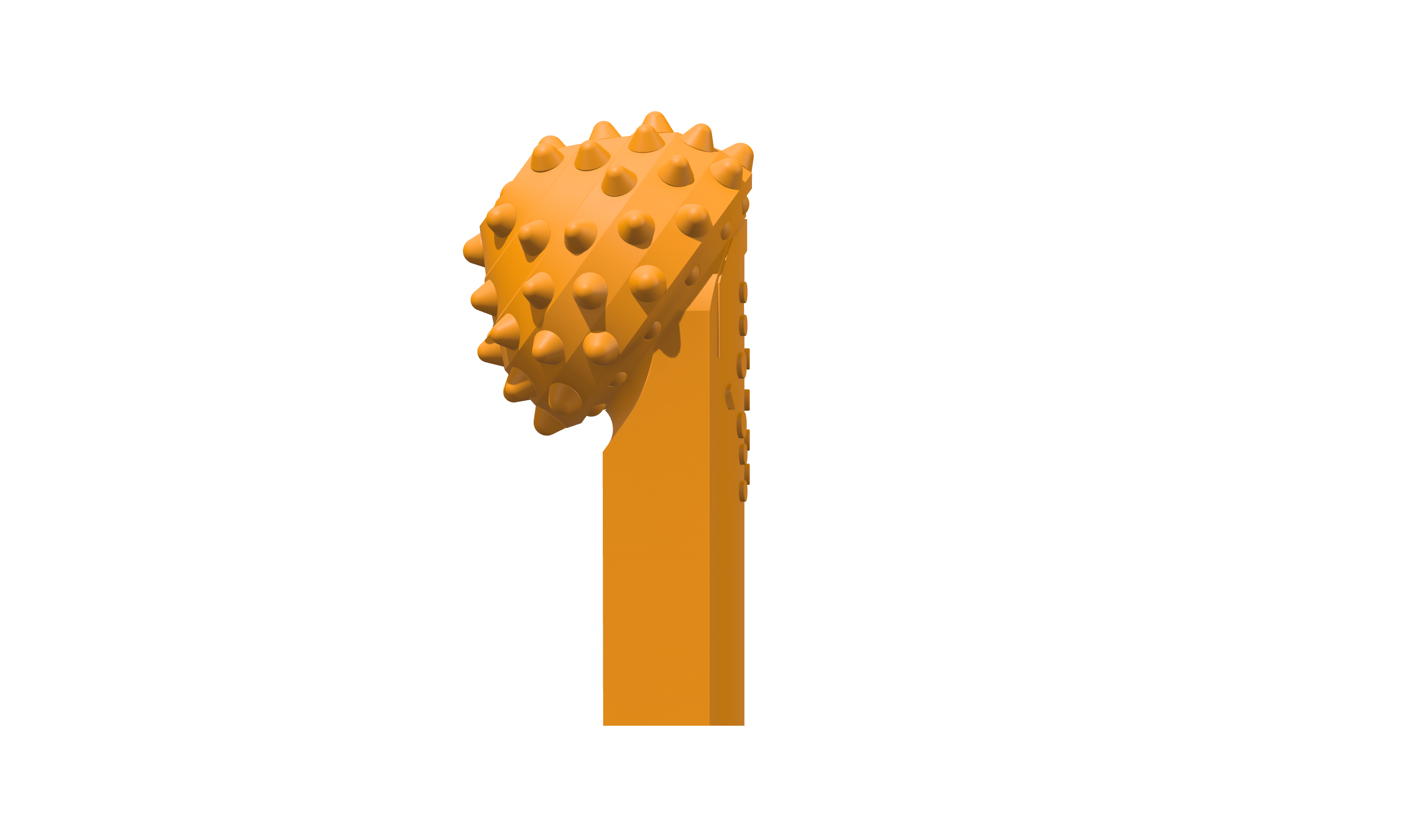
Flat welding face
A regular, flat face replaces the irregular profile. The leg section remains relatively thin.
-
Generation03

Thicker flat leg
The leg section is thicker. Its working angle is set when the bit is positioned for welding.
-
Generation04MH-3 leg
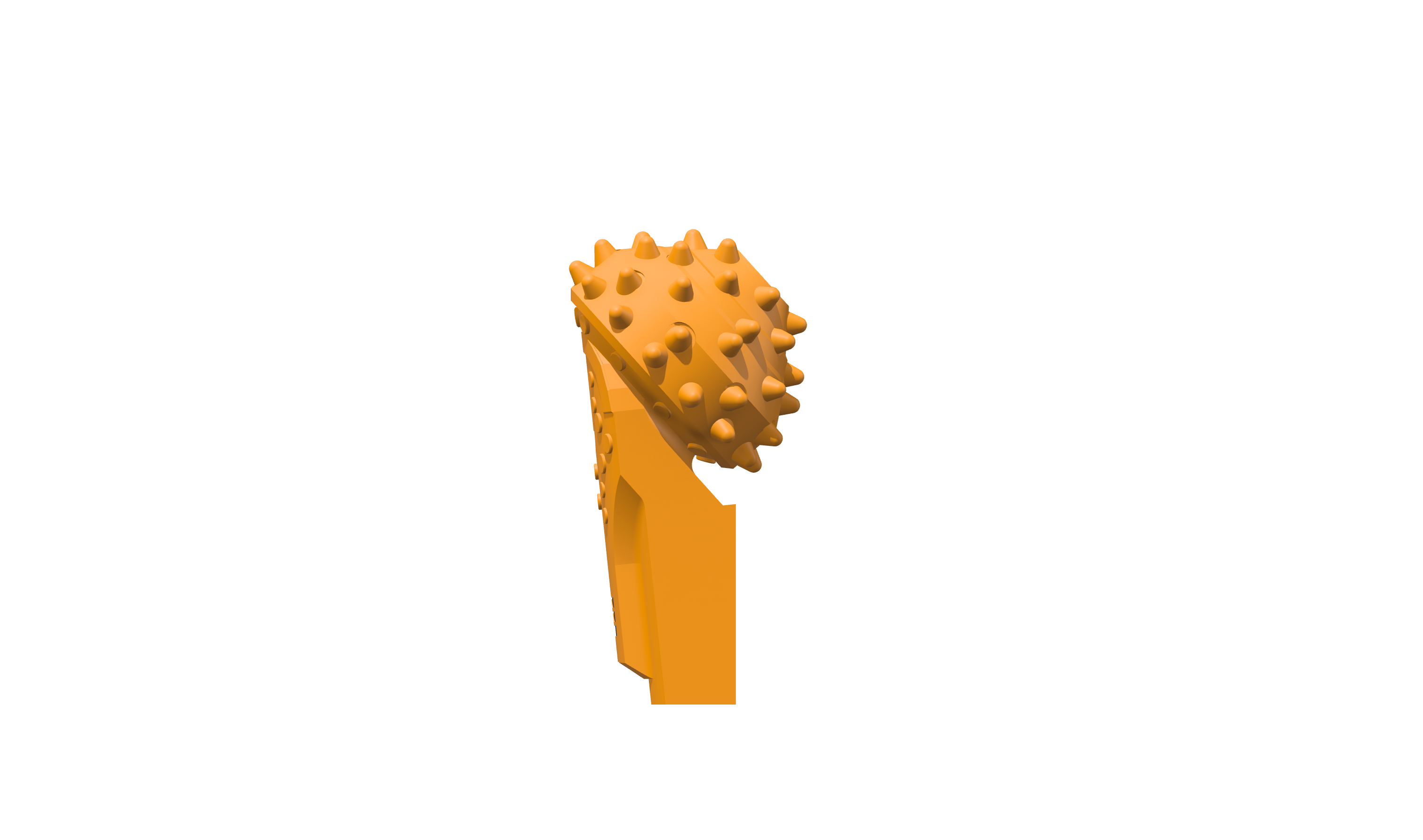
Preset-angle leg
The thicker leg used by MH-3 incorporates the working angle into its shape.
3RD GENERATION → 4TH GENERATION
Where the working angle comes from
These lower-leg details show the difference in geometry and positioning before welding.
Component illustrations and enlarged assembly details are shown at different display scales. The working-angle views explain the geometry; use the tool drawing to set the installation.
Check the position on the complete barrel
The preset leg provides a geometric starting point. Radial position, working height and orientation must still agree around the inner and outer cutting paths. Check the cutting-ring shape and existing openings before fitting replacements, and control heat reaching the sealed assembly during welding.
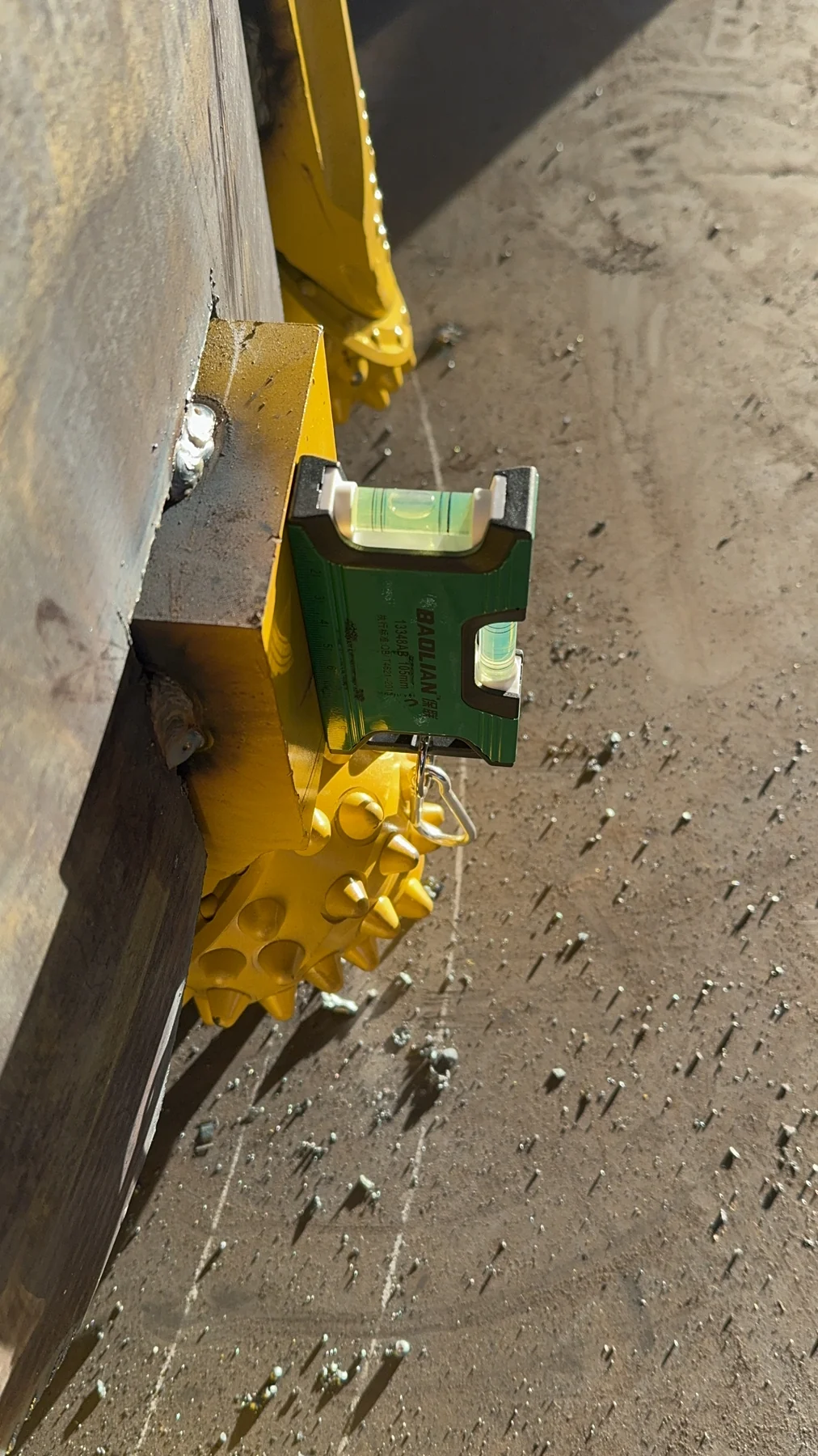
Position
Check the cutter centres against the layout drawing and a common reference.
Clearance
Check the cutting paths, supporting steelwork and space for cuttings to move.
Welding
Follow the agreed procedure and recheck the finished positions after welding.
Choose the cone and the mounting method
| Model | Cone / inserts | Installation difference |
|---|---|---|
| MH-1 | 132 mm; 45 inserts · Ø13 mm | Flat weld-on leg; configuration follows the selected drawing revision. |
| MH-2 | 139 mm; 52 inserts · Ø14 mm | Third-generation cone with the earlier tricone-style weld-on body. |
| MH-3 | 139 mm; 52 inserts · Ø14 mm | Third-generation cone with the thicker, preset-angle piling leg. |
| MH-3C | 139 mm; 52 inserts · Ø14 mm | Replaceable unit in a matched holder; holder installation sets the working position. |
Choose a weld-on arrangement where the site can prepare, position and weld replacement legs. A holder-mounted arrangement changes the maintenance task: a matched roller-bit unit is replaced while the holder stays on the barrel. It does not make different holders interchangeable.
Explore the roller-bit rangeAn MH-3 refit, backed by on-site support
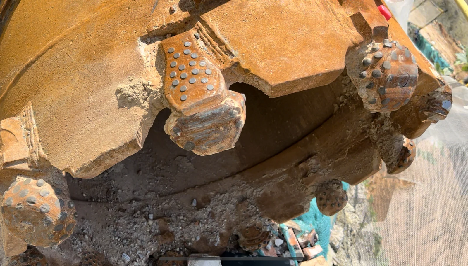
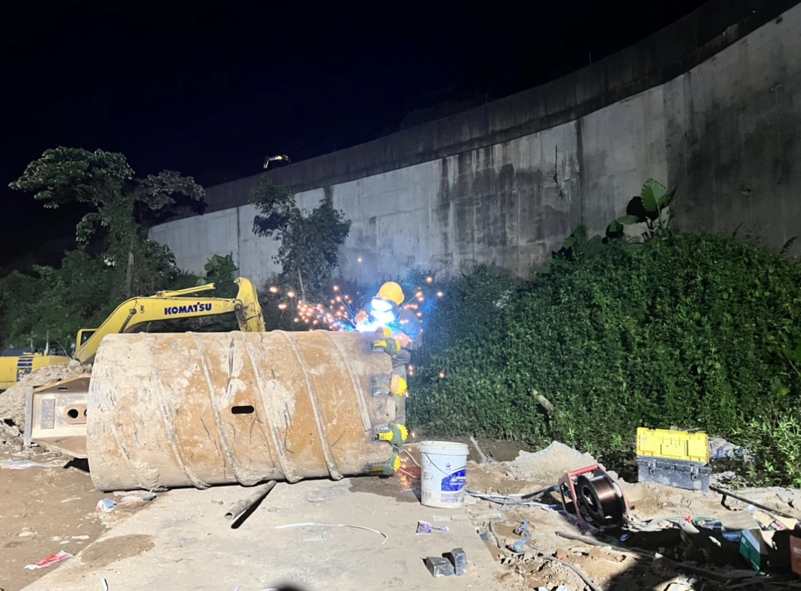
At Zengcheng, the customer reported repeated cone loss and vibration on a barrel and original roller bits supplied by others. Our team helped refit the retained barrel with MH-3 roller bits, guided positioning and welding, and trained the operators.
Follow-up recorded approximately 57 m of cumulative drilling by 31 August 2022. The record includes estimated entries and an incomplete replacement history, so it does not establish the service life of an unchanged ten-bit set. The full case retains the operating notes and position-by-position inspections.
USE & APPLICATION
Work through the practical checks.
Build the configuration around your barrel
Send the barrel diameter, current roller-bit layout, tool photos and ground conditions. State whether you need replacement roller bits, a cutting ring or a complete core barrel.
Request an MH-3 review